
Scope of this technical record
Series-level platform for Unidrive SP/M cases where high-performance vector or servo-like machines need output, braking, control-supply, feedback and thermal evidence before repair decisions.
Secure loads and axes before testing. Do not disconnect feedback or brake-control wiring without understanding machine motion risk.
Unidrive service platform route
Unidrive pages keep feedback and machine evidence visible before power-stage conclusions.
Unidrive platform evidence image
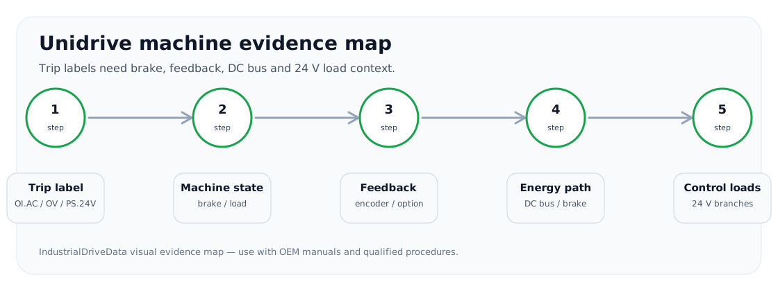
Platform scope
This platform covers the Unidrive service cases most likely to be checked by a repair buyer or maintenance engineer: OI.AC, Over Volts, PS.24V, O.ht and encoder/feedback instability. The service route is different from a general-purpose VFD because feedback devices, option modules and brake timing can create symptoms that look like power-stage faults.
The platform links fault pages to three circuit paths: output current/vector feedback, DC-bus/braking energy, and control-supply/option-module feedback.
Decision routes
The useful question is not only “what does the trip mean?” but “which machine or drive boundary must be proven first?”
Unidrive platform route
| Route | Typical symptoms | Evidence needed |
|---|---|---|
| Output/vector path | OI.AC, feedback instability under load | Motor cable, brake release, encoder direction, current feedback |
| DC-bus/brake path | Over Volts on stop/lowering | Load inertia, brake resistor/chopper, DC-bus trend |
| Control-supply path | PS.24V or option-module instability | External loads, sensor supply, option modules |
| Thermal path | O.ht or cold/hot fan symptoms | Cooling, heatsink, fan, ambient and load duty |
Repair and modernization boundary
Unidrive repair remains valuable where option modules and machine configuration are preserved. Modernization becomes a better path when feedback hardware is obsolete, parameter backup is missing, or repeated faults cannot be reconciled with field evidence.
Field record checklist
- Unidrive family
- Option modules
- Feedback/control mode
- Brake/load evidence
- Repair or modernization outcome
Technical basis and reference documents
This is an independent editorial technical reference. Original manufacturer documentation remains controlling for installation, repair and commissioning decisions.
Public trip-code reference for OI.AC, Over Volts and other Unidrive trips.
Model records
Fault records
Unidrive SP or Unidrive M trips on OI.AC during enable, acceleration, load change or unstable closed-loop operation.
Unidrive trips on Over Volts during deceleration, hoist lowering, winder stop or high line condition.
Unidrive reports PS.24V, loses option/module supply, or drops control logic when external loads are connected.
Unidrive reports O.ht or O.ht1 after load operation, high ambient temperature or poor cabinet cooling.
Closed-loop Unidrive application is unstable, trips under load, hunts, overspeeds or reports feedback-related symptoms.
Board and assembly records
Captures encoder, feedback option, shield/ground, external 24 V load and control-supply evidence for unstable closed-loop or PS.24V cases.
Captures Over Volts and O.ht/O.ht1 evidence around DC bus, braking resistor, chopper, fan, heatsink and load duty.
Circuit and diagnostic records
Routes OI.AC and unstable closed-loop behaviour through motor cable, output bridge, current feedback, brake release, encoder feedback, shielding and tuning context.
Routes Over Volts evidence through line voltage, DC bus, load regeneration, deceleration ramp, brake resistor, brake chopper and feedback-induced instability.
Routes PS.24V, thermal feedback and encoder instability through external 24 V loads, option modules, feedback wiring, sensor supply, heatsink feedback and control-board evidence.
Unidrive SP/M reports OI.AC or trips during enable, acceleration, load change or closed-loop instability.
Unidrive reports Over Volts during deceleration, lowering, stop, winder unwind or unstable closed-loop operation.
Unidrive reports PS.24V, thermal feedback symptoms, O.ht/O.ht1 or feedback instability with option modules and external control wiring.
Turn this record into a qualified service request
A repair decision is much more reliable when the request includes the exact identity of the drive, the first fault evidence and the machine condition when the symptom appeared.
- Complete drive type code / MLFB or nameplate model
- Fault code, fault value and first event before reset
- When the event appears: power-up, enable, ramp, run, decel or stop
- Motor/cable connected or isolated during the symptom
- Visible board, option-card, module and connector identifiers
- Previous repair history, replacement parts and repeat-failure pattern