
Scope of this technical record
Maps Unidrive control-supply, option-module, feedback and thermal-feedback evidence used by PS.24V, O.ht and encoder instability cases.
Do not bypass 24 V protection. Secure machine controls before disconnecting option modules or feedback wiring.
Unidrive control-supply / feedback path
The control-side path supports PS.24V, O.ht and encoder-instability cases.
Unidrive control supply and feedback image
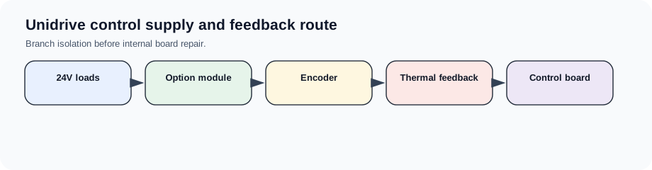
Shared route for supply and feedback faults
PS.24V, thermal feedback and encoder instability often share the same control side: external 24 V loads, option modules, sensor supply, feedback cable, heatsink feedback and the control board. This route keeps those branches visible.
Control-side path table
Branch isolation is more useful than a generic board-swap.
Unidrive control-supply/feedback path
| Branch | Evidence | Route |
|---|---|---|
| External 24 V loads | Fault follows branch | Panel wiring/sensor |
| Option modules | Fault follows module | Module route |
| Feedback device | Supply/noise/direction | Encoder route |
| Heatsink/fan feedback | Cold/hot timing | Thermal route |
| Control board | Fault persists after external proof | Internal evaluation |
Field record checklist
- 24V branches
- Option modules
- Feedback supply
- Thermal feedback
- Control-board boundary
Technical basis and reference documents
This is an independent editorial technical reference. Original manufacturer documentation remains controlling for installation, repair and commissioning decisions.
User-guide reference for control-side and trip context.
Turn this record into a qualified service request
A repair decision is much more reliable when the request includes the exact identity of the drive, the first fault evidence and the machine condition when the symptom appeared.
- Complete drive type code / MLFB or nameplate model
- Fault code, fault value and first event before reset
- When the event appears: power-up, enable, ramp, run, decel or stop
- Motor/cable connected or isolated during the symptom
- Visible board, option-card, module and connector identifiers
- Previous repair history, replacement parts and repeat-failure pattern