
Scope of this technical record
Maps Unidrive output current, vector-control and feedback evidence from output bridge to motor cable, brake, encoder and control loop.
Secure machine motion before testing output or feedback paths.
Unidrive output/vector path
OI.AC requires both output hardware and feedback-loop evidence.
Unidrive output/vector path image
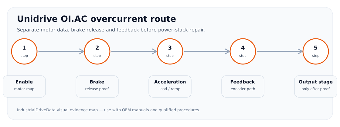
Output path plus feedback loop
Unidrive OI.AC cannot be mapped only as U/V/W output hardware. In closed-loop machines, current demand is shaped by feedback and brake/load behaviour. The path includes output bridge, current feedback, motor cable, brake, motor, encoder, feedback option and vector-control loop.
Path table
Use each node to decide whether the next action is field work or drive repair.
Unidrive output/vector path
| Node | Evidence | Fault route |
|---|---|---|
| Output bridge/current feedback | Trip persists after field proof | Power-stage route |
| Motor cable | Insulation or movement evidence | External path |
| Brake/load | Held brake or jam | Machine path |
| Encoder | Direction/noise/supply | Feedback path |
| Vector loop | Hunting or unstable current | Parameter/tuning route |
Field record checklist
- Output bridge
- Motor cable
- Brake/load
- Encoder
- Control loop
Technical basis and reference documents
This is an independent editorial technical reference. Original manufacturer documentation remains controlling for installation, repair and commissioning decisions.
Turn this record into a qualified service request
A repair decision is much more reliable when the request includes the exact identity of the drive, the first fault evidence and the machine condition when the symptom appeared.
- Complete drive type code / MLFB or nameplate model
- Fault code, fault value and first event before reset
- When the event appears: power-up, enable, ramp, run, decel or stop
- Motor/cable connected or isolated during the symptom
- Visible board, option-card, module and connector identifiers
- Previous repair history, replacement parts and repeat-failure pattern