
Scope of this technical record
Maps Unidrive DC-bus and braking evidence for Over Volts, regenerative load and brake-resistor/chopper decisions.
DC-bus and brake resistor circuits are hazardous. Verify isolation, discharge and load state before access.
Unidrive DC-bus/braking path
The path connects Over Volts to regenerative energy and braking hardware.
Unidrive DC-bus braking path image
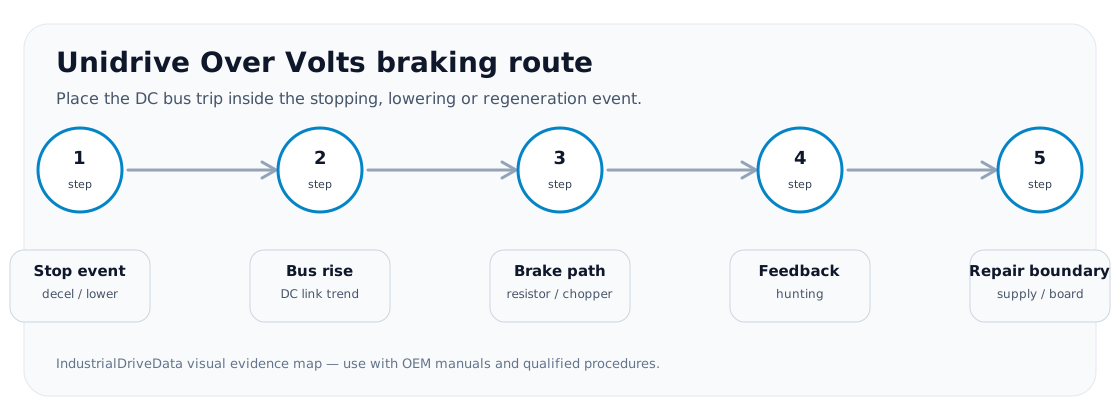
DC bus as an energy balance
The DC bus rises when regenerated or incoming energy exceeds what the drive can store or dissipate. On hoists and winders, this is often a machine-energy route before a hardware route.
Braking path table
The route connects mechanical energy to electrical evidence.
Unidrive DC bus/braking path
| Node | Evidence | Meaning |
|---|---|---|
| Load/inertia | Overhauling or fast stop | Energy source |
| Ramp/profile | Too aggressive decel | Control demand |
| Brake resistor | Open/wrong value/overheated | Dissipation fault |
| Brake chopper | No switching or shorted device | Hardware boundary |
| Bus feedback | Incredible or noisy reading | Sensing boundary |
Field record checklist
- Load energy
- Ramp profile
- Brake resistor
- Chopper
- Bus feedback
Technical basis and reference documents
This is an independent editorial technical reference. Original manufacturer documentation remains controlling for installation, repair and commissioning decisions.
Reference for Over Volts and DC-bus trip context.
Turn this record into a qualified service request
A repair decision is much more reliable when the request includes the exact identity of the drive, the first fault evidence and the machine condition when the symptom appeared.
- Complete drive type code / MLFB or nameplate model
- Fault code, fault value and first event before reset
- When the event appears: power-up, enable, ramp, run, decel or stop
- Motor/cable connected or isolated during the symptom
- Visible board, option-card, module and connector identifiers
- Previous repair history, replacement parts and repeat-failure pattern