
Scope of this technical record
MICROMASTER 430 service routing for fan and pump applications where F0001, F0002 or F0003 appears during start, ramp, stop or weak-supply events.
MICROMASTER drives contain hazardous mains and DC-link energy. Qualified personnel must isolate the supply, prevent unexpected motor movement and verify discharge before terminal or internal inspection.
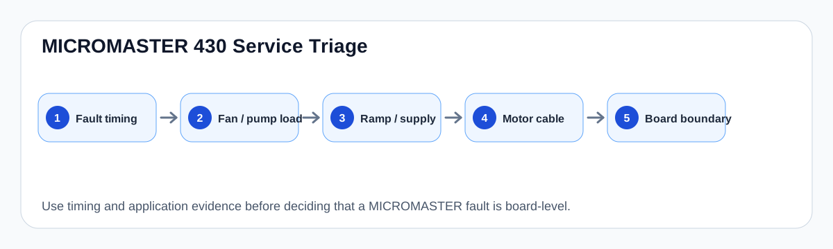
MICROMASTER 430 service triage route
The route keeps fan and pump process evidence visible before F0001, F0002 or F0003 becomes a board claim.
MICROMASTER 430 service triage map
Why this series needs a practical fault route
MICROMASTER 430 is a fan and pump drive platform, so the same fault code often has a process cause as well as an electrical cause. A blocked fan, closed damper, water hammer, pump non-return valve or excessive inertia can create the same operator-panel evidence that a technician might otherwise treat as a failed power board.
The useful page therefore does not begin with parts replacement. It starts by classifying timing: power-up, enable, acceleration, steady run, deceleration, OFF3 fast stop or plant supply dip. Once timing is known, the evidence can be routed to supply/precharge, ramp/load energy, motor/cable, output stage or control measurement.
MICROMASTER 430 first-pass evidence routing
| Indication | Most useful timing split | First boundary to prove |
|---|---|---|
| F0001 overcurrent | Enable / first PWM / acceleration / load | Motor-cable-load path before output module |
| F0002 overvoltage | Ramp-down / OFF3 / high line / active load | Regeneration, ramp and DC-link braking path |
| F0003 undervoltage | Power-up / contactor pull-in / plant sag / load start | Incoming supply, fuses, contactor and precharge |
| A0501 or A0502 preceding trip | Limit warning before shutdown | Ramp, load inertia and parameter context |
Fan and pump evidence that changes the conclusion
Fans and pumps create diagnostic traps. A high-inertia fan can regenerate into the DC link during stop; a pump can overload at start if the process valve or check valve behaves differently than during commissioning; a belt or blocked impeller can make an otherwise healthy inverter report overcurrent.
For this reason, the support record must include the process state at the moment of the trip. The same F0001 event at first enable, during ramp-up, and after a valve changes state should be handled as three different service problems.
- Record the exact state of dampers, valves, belts, pump load and motor direction.
- Preserve ramp and stop-mode settings before changing them.
- Record whether warnings appeared before the fault, especially current-limit or overvoltage-limit warnings.
- Do not treat a repeat trip as a control-board problem until the machine boundary is proven.
How this cluster links into the database
The series page now functions as a hub. F0001 and F0002 share a ramp/load/DC-link route; F0003 has a separate supply/precharge route; the MICROMASTER power-board record asks for photos and measurements that separate field wiring from board repair.
This makes MICROMASTER coverage useful for technicians and maintenance teams: a technician checking a single fault code can land on a specific fault page, while a repair shop can move from the fault to a measurement route and a board evidence checklist.
Field record checklist
- Complete type code and voltage class
- Fault code and trip timing
- Motor nameplate and drive parameter set
- Ramp-up / ramp-down / OFF3 values
- Fan or pump mechanical condition
- Input supply and contactor evidence
- Motor cable and output accessory status
Technical basis and reference documents
This is an independent editorial technical reference. Original manufacturer documentation remains controlling for installation, repair and commissioning decisions.
OEM operating material used for MICROMASTER 430 safety, fault and commissioning context.
Manufacturer reference for parameter, fault and alarm routing around the MM4 platform.
Model records
MICROMASTER 430 is treated here as an installed fan/pump service platform: the important repair question is whether F0001, F0002 or F0003 is being produced by process inertia, ramp settings, motor/cable evidence, input supply, precharge/DC-link behaviour or an internal power-board boundary.
MICROMASTER 440 model coverage focuses on fault cases where the same F0001, F0002 or F0003 code may be caused by motor sizing, parameter mismatch, acceleration/deceleration limits, external 24 V / fieldbus behaviour, cable faults, supply/precharge faults or internal power-board evidence.
The MICROMASTER 430 range controls three-phase AC motor speed in 7.5 kW to 250 kW applications, with strong emphasis on fan and pump operation.
Fault records
MICROMASTER 430 / 440 trips on F0001 during enable, acceleration, fast stop, pump start, fan inertia change or a blocked-load event.
MICROMASTER drive trips on F0002 during ramp-down, OFF3 fast stop, fan coast-down, pump check-valve slam, regenerative load or a high-line condition.
MICROMASTER 430 / 440 trips on F0003 at power-up, after contactor pull-in, when other plant loads start, or during a weak-supply event.
Board and assembly records
Circuit and diagnostic records
Maps the field evidence path for MICROMASTER F0001/F0002 events: mains rectification, DC-link storage, ramp generator demand, load inertia, braking/regen behaviour and the inverter output stage.
Separates external supply loss from internal precharge and DC-link failures when a MICROMASTER drive reports F0003 or shows unstable bus charging.
Most voltage-source AC drives follow a common conversion chain: mains input is rectified to a DC bus, filtered by the DC-link stage and switched through an inverter bridge to produce a controlled three-phase motor output.
A MICROMASTER drive trips on F0001 overcurrent or F0002 overvoltage during start, acceleration, deceleration or OFF3 fast stop.
A MICROMASTER drive reports F0003 undervoltage, resets during start, or loses DC-bus credibility under load.
A drive has been removed from service or is being inspected before commissioning, wiring verification or deeper repair.
Turn this record into a qualified service request
A repair decision is much more reliable when the request includes the exact identity of the drive, the first fault evidence and the machine condition when the symptom appeared.
- Complete drive type code / MLFB or nameplate model
- Fault code, fault value and first event before reset
- When the event appears: power-up, enable, ramp, run, decel or stop
- Motor/cable connected or isolated during the symptom
- Visible board, option-card, module and connector identifiers
- Previous repair history, replacement parts and repeat-failure pattern