
Scope of this technical record
Power-board evidence package for MICROMASTER 430 F0001/F0002/F0003 cases after field supply, load and motor-cable evidence has been captured.
Power-board inspection belongs to qualified electronics repair personnel. Do not power a suspect bridge without current-limited/staged procedure and verified isolation.
MICROMASTER power-board evidence route
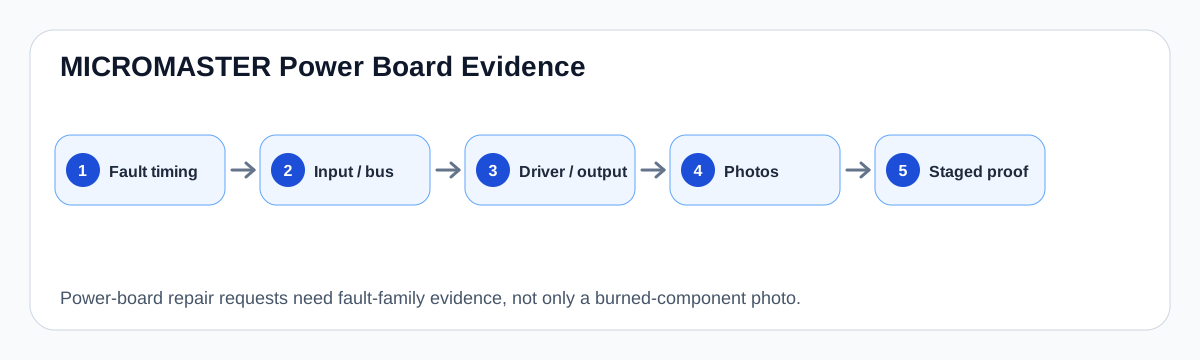
The board record asks for evidence by fault family instead of a single burned-component photo.
MICROMASTER power-board evidence map
What photos and measurements should show
A useful power-board request should show the board as a system: input/rectifier area, precharge components, DC-link capacitors, output module/IGBT area, current-feedback components, gate-driver area and any heat or contamination evidence.
For F0003, the board record should focus on precharge and bus supply. For F0001, it should focus on output-stage, current-feedback and gate-drive evidence. For F0002, it should focus on braking/DC-link and bus-sense evidence where applicable.
Fault-to-board evidence
| Fault | Board area | Evidence requested |
|---|---|---|
| F0001 | Output module / driver / current feedback | Trip timing, module history, channel evidence |
| F0002 | DC link / braking / bus sensing | Ramp context, bus evidence, brake hardware |
| F0003 | Input / rectifier / precharge / capacitors | Input proof, charge behaviour, capacitor state |
| No stable panel | Auxiliary supply loading | Control rail/reset behaviour |
Field record checklist
- Full board photos
- Component-side closeups
- Fault timing
- Field evidence already completed
- Previous replaced parts
- Staged-power test result
Technical basis and reference documents
This is an independent editorial technical reference. Original manufacturer documentation remains controlling for installation, repair and commissioning decisions.
OEM operating material used for MICROMASTER 430 safety, fault and commissioning context.
Manufacturer reference for parameter, fault and alarm routing around the MM4 platform.
Linked circuit records
Maps the field evidence path for MICROMASTER F0001/F0002 events: mains rectification, DC-link storage, ramp generator demand, load inertia, braking/regen behaviour and the inverter output stage.
Separates external supply loss from internal precharge and DC-link failures when a MICROMASTER drive reports F0003 or shows unstable bus charging.
Turn this record into a qualified service request
A repair decision is much more reliable when the request includes the exact identity of the drive, the first fault evidence and the machine condition when the symptom appeared.
- Complete drive type code / MLFB or nameplate model
- Fault code, fault value and first event before reset
- When the event appears: power-up, enable, ramp, run, decel or stop
- Motor/cable connected or isolated during the symptom
- Visible board, option-card, module and connector identifiers
- Previous repair history, replacement parts and repeat-failure pattern