
Scope of this technical record
DC-link, ramp and regenerative-energy path used to interpret MICROMASTER F0001 and F0002 events on fan and pump loads.
DC-link measurements and brake-path work require qualified personnel, isolation and discharge verification.
MICROMASTER ramp and DC-link energy route
The same ramp/load event can produce current-limit or bus-overvoltage evidence.
MICROMASTER DC-link ramp energy image
Path description
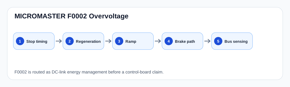
The route begins with AC input and rectification, moves through the DC-link capacitor bank, and then reaches the ramp generator and inverter output bridge. During acceleration the current boundary is stressed; during deceleration the DC-link voltage boundary is stressed.
This is why F0001 and F0002 are paired in one workflow. Both can be symptoms of the same process: a ramp profile or load condition that pushes energy faster than the drive and connected machine can manage.
Evidence to capture
A technician should record acceleration and deceleration times, OFF3 ramp, load inertia, brake hardware and whether the trip follows a current-limit or overvoltage-limit warning. That evidence determines whether the next move is parameter review, process correction, brake hardware inspection or bench-level output-stage repair.
Field record checklist
- P1120 acceleration
- P1121 deceleration
- P1135 OFF3 ramp
- Load inertia
- Brake hardware
- A0501/A0502 warnings
- Output-stage history
Technical basis and reference documents
This is an independent editorial technical reference. Original manufacturer documentation remains controlling for installation, repair and commissioning decisions.
OEM operating material used for MICROMASTER 430 safety, fault and commissioning context.
Manufacturer reference for parameter, fault and alarm routing around the MM4 platform.
Turn this record into a qualified service request
A repair decision is much more reliable when the request includes the exact identity of the drive, the first fault evidence and the machine condition when the symptom appeared.
- Complete drive type code / MLFB or nameplate model
- Fault code, fault value and first event before reset
- When the event appears: power-up, enable, ramp, run, decel or stop
- Motor/cable connected or isolated during the symptom
- Visible board, option-card, module and connector identifiers
- Previous repair history, replacement parts and repeat-failure pattern