
Scope of this technical record
Input, rectifier, precharge and DC-bus supply path used when MICROMASTER F0003 or no-stable-bus symptoms appear.
Input and DC-link evidence must be collected under approved high-voltage procedures; undervoltage displays are not proof of safe internal voltage.
MICROMASTER input and precharge route
The input/precharge route prevents supply faults from being misread as keypad or control-board faults.
MICROMASTER input precharge image
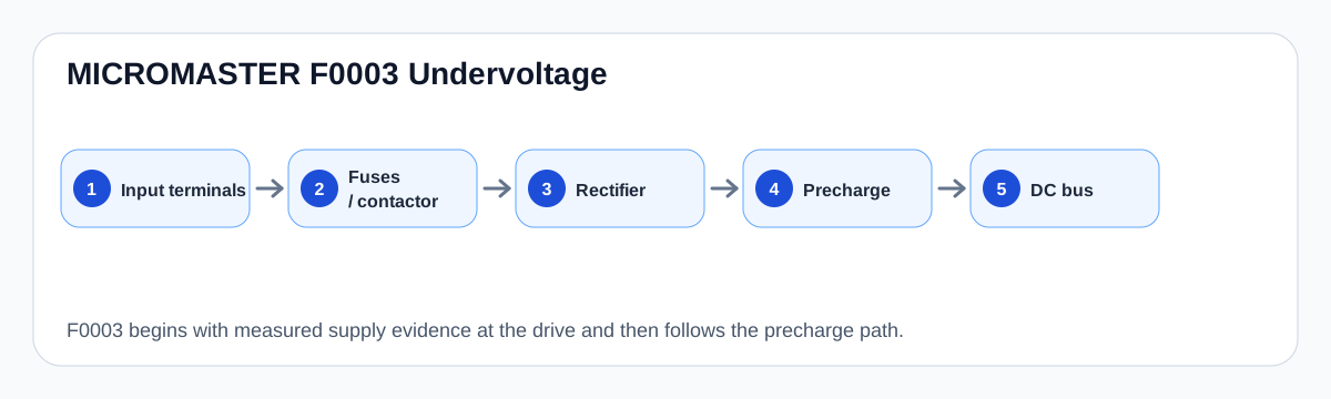
Path description
The F0003 path starts at the incoming terminals and proceeds through protective devices, contactor poles, rectification, precharge and capacitor storage before reaching DC-bus sensing. Each part can create undervoltage evidence.
This path also explains why a supply problem can look like a control problem. If the bus collapses, the operator panel and logic supply may reset even when the original cause is outside the drive.
Input/precharge evidence map
| Node | Useful observation | Decision value |
|---|---|---|
| Input terminals | All phases and voltage present | External supply cleared or not |
| Fuse / contactor | Heat, loose pole, voltage drop | Field repair before drive repair |
| Precharge | Charge event, relay/resistor evidence | Internal energy route |
| DC-link capacitor bank | Charge retention, sag, ripple evidence | Capacitor/precharge boundary |
Field record checklist
- Input voltage at drive
- Contactor/fuse status
- Precharge relay/resistor evidence
- Bus charge behaviour
- Control reset timing
- Capacitor age/condition
Technical basis and reference documents
This is an independent editorial technical reference. Original manufacturer documentation remains controlling for installation, repair and commissioning decisions.
OEM operating material used for MICROMASTER 430 safety, fault and commissioning context.
Manufacturer reference for parameter, fault and alarm routing around the MM4 platform.
Turn this record into a qualified service request
A repair decision is much more reliable when the request includes the exact identity of the drive, the first fault evidence and the machine condition when the symptom appeared.
- Complete drive type code / MLFB or nameplate model
- Fault code, fault value and first event before reset
- When the event appears: power-up, enable, ramp, run, decel or stop
- Motor/cable connected or isolated during the symptom
- Visible board, option-card, module and connector identifiers
- Previous repair history, replacement parts and repeat-failure pattern