
Scope of this technical record
F0002 overvoltage on MICROMASTER drives during ramp-down, OFF3 fast stop, fan coast-down, pump pressure events or high incoming line voltage.
DC-link overvoltage work involves stored energy. Verify discharge before internal inspection and do not defeat braking or overvoltage protection for a production test.
MICROMASTER F0002 overvoltage route
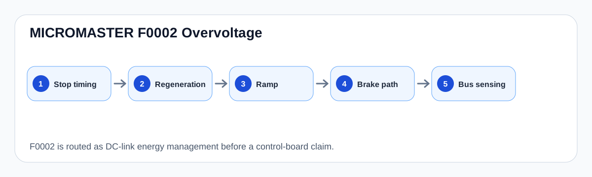
F0002 is treated as a DC-link energy event before board replacement.
F0002 DC-link energy map
What F0002 is really asking
F0002 asks why the DC-link voltage exceeded its safe operating boundary. In most field cases, the answer is not a bad keypad or a random control-board fault; it is excessive regenerated energy, a short deceleration ramp, a missing or failed braking path, high line voltage, or abnormal DC-bus feedback.
The most important split is idle/power-up versus deceleration-only. A trip only on ramp-down belongs first to machine energy and braking route. A trip at power-up or idle needs input-voltage and DC-bus sensing evidence.
F0002 diagnostic split
| When F0002 occurs | First evidence | Likely route |
|---|---|---|
| Normal stop or OFF3 | Ramp-down time and load inertia | Regenerative energy |
| High-inertia fan coast-down | Fan speed, damper state, braking duty | Brake path / DC-link energy |
| Pump process event | Valve/check-valve/water-hammer condition | Mechanical energy and stop profile |
| Power-up or idle | Incoming voltage and bus sensing | Supply/DC-bus measurement path |
Service decision
The first correction may be a ramp or process correction, not a board repair. However, if a braking transistor, resistor or DC-link measurement problem is suspected, the drive should be isolated and assessed before another loaded stop test.
A useful record includes P1121/P1135 stop behaviour, load inertia, brake-resistor installation, whether F0002 follows A0502, and whether the event is repeatable only under process load.
Field record checklist
- Ramp-down and OFF3 values
- Load inertia/process state
- Incoming voltage
- Brake resistor/chopper evidence
- A0502 warning before fault
- Whether the fault is deceleration-only
Technical basis and reference documents
This is an independent editorial technical reference. Original manufacturer documentation remains controlling for installation, repair and commissioning decisions.
OEM operating material used for MICROMASTER 430 safety, fault and commissioning context.
Manufacturer reference for parameter, fault and alarm routing around the MM4 platform.
Diagnostic workflow
Turn this record into a qualified service request
A repair decision is much more reliable when the request includes the exact identity of the drive, the first fault evidence and the machine condition when the symptom appeared.
- Complete drive type code / MLFB or nameplate model
- Fault code, fault value and first event before reset
- When the event appears: power-up, enable, ramp, run, decel or stop
- Motor/cable connected or isolated during the symptom
- Visible board, option-card, module and connector identifiers
- Previous repair history, replacement parts and repeat-failure pattern