
Scope of this technical record
F0001 overcurrent on MICROMASTER 430/440 platforms, especially trips at enable, acceleration, first PWM, load change or after previous module repair.
Stop reset attempts if the trip is immediate or the motor/cable condition is unknown. Output isolation and bridge checks require qualified procedures and verified DC-link discharge.
MICROMASTER F0001 overcurrent route
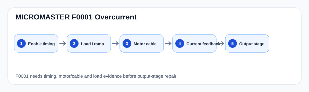
F0001 is split by trip timing before the output bridge is treated as failed.
F0001 overcurrent timing map
Meaning after timing is known
F0001 means the drive has detected overcurrent, but the code alone does not identify the failed part. The route changes depending on whether the fault occurs before the motor turns, at first PWM, during acceleration, after a valve/damper event, or only at full load.
For MICROMASTER fan and pump duty, the machine boundary must stay visible. Stuck loads, incorrect motor data, short acceleration time, cable leakage, output accessories and a damaged final stage can all converge on F0001.
F0001 timing-to-boundary matrix
| Trip timing | Likely first boundary | Stop condition |
|---|---|---|
| Immediately at enable | Output bridge, motor-cable short, ground fault | Do not keep resetting |
| At first PWM only | Motor/cable/output accessory path | Do not test with unknown cable |
| During acceleration | Ramp, load inertia, motor data, current limit | Do not shorten ramp further |
| After repair or module replacement | Gate driver, current feedback, driver supply | Do not energize another module without pre-power checks |
Evidence sequence
Preserve the fault history and trip timing first. Then compare motor rating and parameter data, inspect the mechanical load, and test the motor/cable boundary using drive-safe procedures. Only after the external output path is credible should the power-board route be used.
A repair request should state whether the drive trips with the motor connected, whether the trip disappears with a safe test load or isolated output, and whether any power semiconductor has already been replaced. Those facts decide whether the case belongs to the field technician or bench repair.
Field record checklist
- Trip timing
- Motor data versus drive data
- Acceleration time
- Motor/cable insulation result
- Load condition
- Previous module repair
- Current-limit warning before trip
Technical basis and reference documents
This is an independent editorial technical reference. Original manufacturer documentation remains controlling for installation, repair and commissioning decisions.
OEM operating material used for MICROMASTER 430 safety, fault and commissioning context.
Manufacturer reference for parameter, fault and alarm routing around the MM4 platform.
Diagnostic workflow
Turn this record into a qualified service request
A repair decision is much more reliable when the request includes the exact identity of the drive, the first fault evidence and the machine condition when the symptom appeared.
- Complete drive type code / MLFB or nameplate model
- Fault code, fault value and first event before reset
- When the event appears: power-up, enable, ramp, run, decel or stop
- Motor/cable connected or isolated during the symptom
- Visible board, option-card, module and connector identifiers
- Previous repair history, replacement parts and repeat-failure pattern