
Scope of this technical record
Step-by-step PowerFlex workflow for F12 and F13 events where the sequence must protect the output stage and preserve motor/cable evidence.
Stop if the motor/cable cannot be isolated or the driven machine cannot be secured. Do not repeat-start a suspected short or ground path.
PowerFlex F12 / F13 workflow route
The workflow protects the output stage by proving the external path first.
PowerFlex F12/F13 workflow image
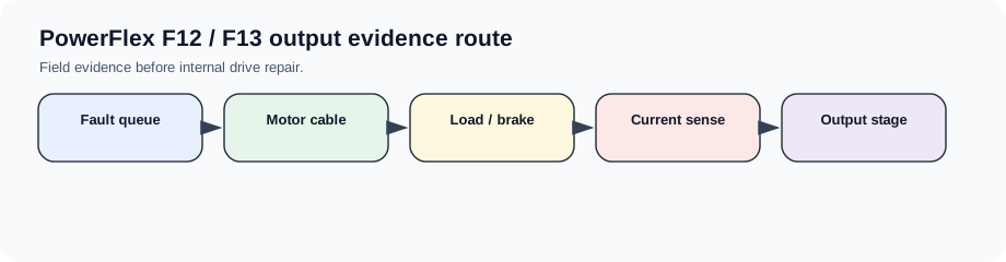
Workflow goal
The workflow decides whether the first repair boundary is field wiring, motor/load, current sensing, gate-driver/output module or a previous repair error. It is deliberately ordered so an unresolved external fault does not destroy a replacement drive.
Step sequence
The same sequence supports F12-only, F13-only and mixed F12/F13 events.
F12/F13 workflow
| Step | Action | Stop condition |
|---|---|---|
| 1 | Record fault queue and exact machine cycle | First fault unknown |
| 2 | Inspect motor cable, terminal box, brake/load | Moisture, ground or jam found |
| 3 | Isolate and test motor/cable under qualified procedure | Isolation cannot be done safely |
| 4 | Compare behaviour with external path proven | Fault persists with output path cleared |
| 5 | Escalate output bridge/current feedback/gate driver | Previous replacement history unclear |
Output package
The completed workflow should produce either a field repair instruction or a drive repair request with enough evidence to evaluate the output stage without guessing.
Field record checklist
- Fault order
- Machine-cycle timing
- External output proof
- Current/ground evidence
- Escalation reason
Technical basis and reference documents
This is an independent editorial technical reference. Original manufacturer documentation remains controlling for installation, repair and commissioning decisions.
OEM safety and fault-handling reference context.
Linked records
The hardware current protection has detected a severe current event. The first split is motor/cable/load versus output bridge, gate-driver, current sensor or power-module damage.
The drive has detected output current imbalance or leakage to ground. The route begins with motor, cable, moisture, output terminals and output-stage evidence.
Routes F12 and F13 evidence through output bridge, current sensing, motor cable, motor insulation, grounding/shielding and mechanical load conditions.
Turn this record into a qualified service request
A repair decision is much more reliable when the request includes the exact identity of the drive, the first fault evidence and the machine condition when the symptom appeared.
- Complete drive type code / MLFB or nameplate model
- Fault code, fault value and first event before reset
- When the event appears: power-up, enable, ramp, run, decel or stop
- Motor/cable connected or isolated during the symptom
- Visible board, option-card, module and connector identifiers
- Previous repair history, replacement parts and repeat-failure pattern