
Scope of this technical record
Workflow for Danfoss VLT Alarm 14 and Alarm 16 cases where the service technician must preserve the fault, classify timing, prove the motor/cable/output boundary and decide when the case becomes a drive-side repair request.
This workflow assumes qualified drive-service access. Lock out supply, verify DC-link discharge and isolate the output correctly. Never megger through the drive and never use repeated restart attempts as the diagnostic method for a suspected earth or short fault.
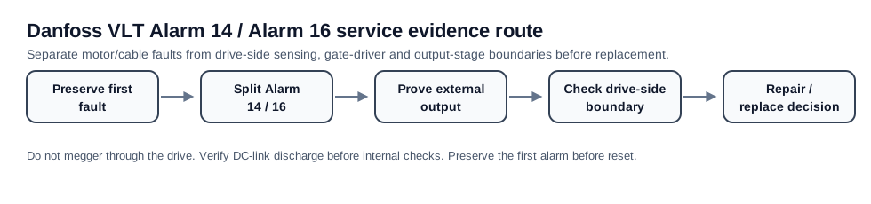
Danfoss Alarm 14 / 16 workflow route
The workflow ends in field repair, drive repair or replacement planning, not just another fault-code definition.
Danfoss Alarm 14 / 16 workflow image
Workflow outcome matrix
The workflow should end with a field repair, drive-side repair request or replacement decision, not just an alarm definition.
| Workflow result | Likely route | Required proof |
|---|---|---|
| Alarm follows motor/cable | Field installation repair | Insulation and terminal evidence |
| Alarm remains output-isolated | Drive-side repair | Current sensor, module or driver evidence |
| Repeat after repair | Cause review | Previous parts and channel checks |
Workflow outcome
The workflow has one goal: produce a defendable boundary decision. At the end of the route, the case should be classified as external motor/cable repair, field wiring/accessory correction, drive-side sensing/output-stage repair, or replacement/retrofit planning. If the workflow only ends with “Alarm 14” or “Alarm 16”, it has not done its job.
Step 1 — preserve the first fault and timing
Record the first alarm before reset, then capture the operating condition. Note whether the event appears at power-up, enable, first PWM, acceleration, steady load, deceleration, after washdown, after a long stop, or after a previous repair. For Alarm 14, environment and moisture matter. For Alarm 16, instant timing and prior output-stage work matter.
Step 2 — separate earth route from short route
Alarm 14 routes toward leakage-to-earth evidence: motor insulation, cable shield, gland sealing, motor terminal box and PE path. Alarm 16 routes toward phase-to-phase or output short evidence: U/V/W wiring, output contactor, motor leads, phase insulation and static output-stage condition. The two routes share the same output zone but the evidence emphasis is different.
Workflow branch split
| Branch | Primary evidence | Escalates when |
|---|---|---|
| Alarm 14 earth fault | Motor/cable-to-earth and environmental evidence | External path is isolated and alarm persists |
| Alarm 16 short circuit | Phase-to-phase/output-terminal and static output evidence | External output is clear and alarm persists |
| Both alarms appear | Fault queue and first event order | Evidence points to output module, driver or current path |
Step 3 — prove external output path before drive repair
Inspect and document output terminals, cable glands, shield/PE routing, motor terminal box, output contactors and filters. Perform insulation and continuity checks only after the output is correctly isolated from the drive. If the fault follows the motor or cable, repair the field installation first. If the alarm remains with the external path proven clear, stop field retests and build a drive-side evidence package.
Step 4 — define drive-side repair boundary
A drive-side case should identify whether the likely boundary is current detection, output module, gate-driver command/protection, power-board contamination or previous repair. This distinction matters because a module replacement without driver and feedback proof can fail again.
- For Alarm 14, document current-sensor and output leakage evidence if the external path is clear
- For Alarm 16, document static output bridge, gate-driver and current-feedback evidence
- For repeat failures, collect photos of failed parts and previous repair areas before energizing again
- For old or scarce frames, prepare a repair versus replacement decision after the evidence boundary is known
Field record checklist
- First fault and timing
- Alarm 14/16 branch classification
- Motor/cable/output proof
- Environmental or vibration pattern
- Disconnected-output result
- Drive-side board/module evidence if escalated
Technical basis and reference documents
This is an independent editorial technical reference. Original manufacturer documentation remains controlling for installation, repair and commissioning decisions.
Used to anchor Alarm 14 around motor/cabling isolation and the boundary where current-sensor or drive-side investigation becomes relevant.
Used to anchor Alarm 14 as short-to-ground in motor/wiring and Alarm 16 as line-to-line short circuit in motor/wiring.
Used as FC-family public manual context for alarm wording, DC-link safety and output-side service boundaries.
Linked records
The drive has detected an earth/ground fault path. The first split is motor/cable insulation versus output-stage leakage or damaged power electronics.
The fault route is output short-circuit evidence: cable, motor, output terminals, output accessories, IGBT module and driver/current-sense circuitry.
Routes alarm 14 and alarm 16 through output insulation, terminal contamination, motor cable damage, IGBT module, gate driver and current-feedback path.
Turn this record into a qualified service request
A repair decision is much more reliable when the request includes the exact identity of the drive, the first fault evidence and the machine condition when the symptom appeared.
- Complete drive type code / MLFB or nameplate model
- Fault code, fault value and first event before reset
- When the event appears: power-up, enable, ramp, run, decel or stop
- Motor/cable connected or isolated during the symptom
- Visible board, option-card, module and connector identifiers
- Previous repair history, replacement parts and repeat-failure pattern