
Scope of this technical record
Functional output path for Danfoss VLT earth-fault and short-circuit cases, linking the inverter bridge, current detection, U/V/W terminals, motor cable, motor insulation, PE route and field accessories into one diagnostic map.
The output path remains tied to hazardous DC-link energy and motor circuit hazards. Isolate power and verify discharge before internal inspection. Keep insulation testing outside the drive electronics by correctly disconnecting the motor/cable route.
Danfoss output earth/short path
The same output path explains why Alarm 14 and Alarm 16 overlap but require different evidence.
Danfoss output earth/short path image
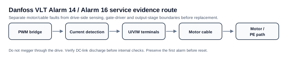
Why the output path is the shared route for Alarm 14 and Alarm 16
Alarm 14 and Alarm 16 both live on the output side, but they read different evidence from that path. Alarm 14 asks where current is leaking to earth. Alarm 16 asks where phase-to-phase or output short current is being detected. A circuit-path page keeps those questions connected without collapsing them into one fault definition.
The functional path begins at the PWM output bridge and current detection. It then passes through U/V/W terminals, output accessories, cable run, cable shield, motor terminal box, motor winding insulation and protective earth. Every point can create a field fault that looks like a drive failure until it is proven otherwise.
Functional path and evidence points
A good diagnostic path records evidence in physical order. Do not start at the module if the cable glands, terminal box and output contactor have not been inspected. Do not replace a current sensor if the motor insulation result is unknown. The path is designed to prevent a field wiring issue from becoming a repeat drive repair.
Danfoss VLT output earth/short path
| Path area | Alarm 14 relevance | Alarm 16 relevance |
|---|---|---|
| Current detection | May report earth leakage or biased zero condition | May report output current surge |
| Output bridge | Possible leakage or damaged semiconductor path | Possible shorted IGBT leg or driver-induced fault |
| U/V/W terminals | Contamination or tracking to PE | Loose strands or phase-to-phase contact |
| Motor cable | Wet/damaged insulation to shield/earth | Crushed cable or phase-to-phase failure |
| Motor terminal box | Moisture and tracking to frame | Phase lead damage or incorrect termination |
| Output accessories | Filter/contactor leakage path | Contactor/filter short or wiring error |
Boundary conditions
If the external output path is proven faulty, the drive-side path is not the first repair. If the external path is proven clear and the alarm remains, the repair request should document the bridge, gate-driver and current-detection evidence. The same diagram therefore supports both field troubleshooting and workshop intake.
- Alarm follows motor/cable: repair field installation before replacing the drive
- Alarm remains with external output isolated: build drive-side output/sensing evidence
- Alarm appears after module repair: verify driver and current feedback before another power test
- Alarm appears only with moisture/vibration: preserve environmental proof before disassembly
Field record checklist
- Output terminal photos
- Cable and gland condition
- Motor terminal-box evidence
- Insulation path evidence
- Current-detection/module photos if escalated
- Previous repair history
Technical basis and reference documents
This is an independent editorial technical reference. Original manufacturer documentation remains controlling for installation, repair and commissioning decisions.
Used to anchor Alarm 14 around motor/cabling isolation and the boundary where current-sensor or drive-side investigation becomes relevant.
Used to anchor Alarm 14 as short-to-ground in motor/wiring and Alarm 16 as line-to-line short circuit in motor/wiring.
Used as FC-family public manual context for alarm wording, DC-link safety and output-side service boundaries.
Turn this record into a qualified service request
A repair decision is much more reliable when the request includes the exact identity of the drive, the first fault evidence and the machine condition when the symptom appeared.
- Complete drive type code / MLFB or nameplate model
- Fault code, fault value and first event before reset
- When the event appears: power-up, enable, ramp, run, decel or stop
- Motor/cable connected or isolated during the symptom
- Visible board, option-card, module and connector identifiers
- Previous repair history, replacement parts and repeat-failure pattern