
Scope of this technical record
Danfoss VLT Alarm 16 short-circuit route for deciding whether the trip comes from motor wiring, output cable damage, terminal short, output contactor, IGBT module, gate-driver channel, current detection or a previous repair that was powered before the short route was proven.
Alarm 16 can indicate a destructive output fault. Do not clear and restart repeatedly. Isolate power, verify DC-link discharge and prove the motor/cable/output-terminal boundary before any internal output-stage decision. Do not insulation-test through the drive.
Danfoss Alarm 16 short-circuit route
Alarm 16 is treated as destructive until the external output path and drive-side output stage are separated.
Danfoss Alarm 16 short-circuit decision image
Alarm 16 service decision matrix
Alarm 16 users need to separate motor wiring and output accessories from output module, gate-driver and current-detection evidence before another powered test.
| Observed situation | Decision needed | Evidence to collect |
|---|---|---|
| Instant at run | External output or drive-side short | U/V/W, motor cable, static output evidence |
| After module repair | Repeat-failure cause | Gate-driver and current-feedback evidence |
| With output isolated | Drive-side boundary | Disconnected-output result and module/board photos |
Alarm 16 is a short-circuit route before it is a module quote
Danfoss service summaries identify Alarm 16 as a short circuit in the motor or motor wiring. That public wording is deliberately conservative: the drive may be protecting itself from a real output short, and a repeated powered test can convert a diagnosable wiring fault into a failed output bridge.
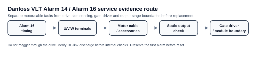
The service task is to determine whether the short path is outside the drive or inside the inverter output stage. The first evidence should be the exact timing, U/V/W terminal condition, output accessories, motor-cable inspection and motor isolation result. Only after those are proven should the case move to IGBT module, gate-driver and current-detection evidence.
Alarm 16 timing map
Alarm 16 at enable, first PWM, acceleration or after module replacement has different meaning. A short that appears before the motor rotates is far more likely to be wiring, terminal, output accessory or drive-side output hardware than a process-load issue. A short that appears after previous repair needs a pre-power gate-driver and current-feedback review before another energized trial.
Alarm 16 first diagnostic boundary
| Alarm 16 pattern | First boundary | Evidence to collect |
|---|---|---|
| Instant at run command | Output terminals and motor cable | U/V/W inspection, loose strands, crushed cable, contactor state |
| At first PWM with motor connected | Motor winding or cable phase-to-phase path | Motor/cable isolation and phase-to-phase insulation evidence |
| With motor cable disconnected at drive | Drive-side output module / driver / current path | Static output evidence and repair boundary photos |
| After IGBT/module replacement | Unproven gate-driver or external short | Gate-driver channel checks, current feedback, failed-part history |
| Intermittent with vibration | Cable movement, output accessory or terminal contact | Cable chain, contactor, terminal torque and movement-specific repeatability |
External short proof comes before power-stage work
The external output path includes the drive output terminals, motor cable, output contactors, filters, motor terminal box and motor windings. Any accessory between the drive and motor can make Alarm 16 look like a drive failure. Photographs and isolation results matter because a repaired power stage can fail immediately if an output contactor, cable or winding fault remains.
If the external output path is proven clear and Alarm 16 remains with a documented disconnected-output test, the case becomes a drive repair request. The suspected boundary is no longer a generic “board”: it may be a shorted IGBT leg, gate-driver command fault, desaturation/protection feedback problem, current transformer path or contamination between output hardware.
- Preserve the original fault queue before clearing alarms
- Photograph U/V/W terminals and all output accessories
- Record whether the alarm changes with the output removed at the drive terminals
- Do static checks only under a qualified discharge and isolation procedure
- Do not fit another power module until gate-driver/current-feedback evidence is reconciled
Repair versus replacement decision
A one-time Alarm 16 caused by a clear motor cable short is a field repair case, not a drive replacement case. Alarm 16 that remains without the external output path, or Alarm 16 after a prior module replacement, is a bench or board-level case. The replacement decision depends on frame size, availability, production risk and whether the root cause was proven.
Alarm 16 repair decision matrix
| Evidence result | Likely route | Do not do this |
|---|---|---|
| Short found in cable or terminal box | Repair external path, then controlled retest | Replace the drive first |
| No external short; alarm remains | Power-stage / driver / sensing investigation | Keep resetting under power |
| Module recently failed again | Gate-driver and feedback pre-power review | Fit another module without cause proof |
| Old frame with scarce parts | Repair/replace/retrofit decision after evidence | Quote by series name only |
Field record checklist
- VLT type code and frame
- Alarm 16 first-fault timing
- U/V/W terminal and accessory photos
- Motor/cable phase and insulation evidence
- Disconnected-output result
- Gate-driver/module/current path evidence if escalated
Technical basis and reference documents
This is an independent editorial technical reference. Original manufacturer documentation remains controlling for installation, repair and commissioning decisions.
Used to anchor Alarm 14 around motor/cabling isolation and the boundary where current-sensor or drive-side investigation becomes relevant.
Used to anchor Alarm 14 as short-to-ground in motor/wiring and Alarm 16 as line-to-line short circuit in motor/wiring.
Used as FC-family public manual context for alarm wording, DC-link safety and output-side service boundaries.
Diagnostic workflow
Turn this record into a qualified service request
A repair decision is much more reliable when the request includes the exact identity of the drive, the first fault evidence and the machine condition when the symptom appeared.
- Complete drive type code / MLFB or nameplate model
- Fault code, fault value and first event before reset
- When the event appears: power-up, enable, ramp, run, decel or stop
- Motor/cable connected or isolated during the symptom
- Visible board, option-card, module and connector identifiers
- Previous repair history, replacement parts and repeat-failure pattern