
Scope of this technical record
Routes PowerFlex F81-F86 DPI/HIM port-loss cases through port identity, connected device, cable, adapter, cabinet noise and control-board boundary.
A port-loss event may affect start/stop source, speed reference and machine status. Do not mask the fault action without controls and safety review.
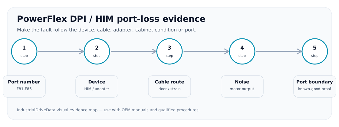
DPI / HIM port-loss route
Make the fault follow the device, cable, route or port before replacing control hardware.
DPI / HIM port-loss evidence image
Service decision coverage
DPI port-loss pages must help users find the port boundary. This panel forces the fault to follow a cable, HIM, adapter, cabinet condition or drive port.
| Observed situation | Decision needed | Evidence that satisfies the case |
|---|---|---|
| Fault follows HIM/adapter | External device fault | Swap result and device identity |
| Fault follows door movement | Cable or harness issue | Route photo and flex evidence |
| Fault appears during motor output | Noise/routing issue | Cable separation and grounding evidence |
Why the port number matters
F81-F86 is not one fault. The number identifies a port/device route. A useful report says which HIM, cable, TCOMM, network adapter or peripheral was connected and whether the fault follows that device or remains with the drive port.
The physical installation is often as important as the electronics. Door-mounted HIM cables, motor-lead proximity, poor shield terminations and cabinet noise can create intermittent port loss that looks like a failed board.
DPI/HIM diagnostic split
The safest route is to make the fault follow a removable boundary before replacing drive hardware.
Port-loss evidence matrix
| Evidence | Interpretation | Next action |
|---|---|---|
| Fault follows HIM | Operator interface or connector issue | Inspect/replace HIM after parameter backup |
| Fault follows cable | Cable damage, routing or door flex | Reroute or replace cable |
| Fault follows adapter | TCOMM/network device issue | Check adapter and power/network state |
| Fault appears with motor load/noise | EMC/grounding problem | Review cable segregation and grounding |
| Fault remains on same drive port | Port/control-board boundary | Prepare repair request with device tests |
Evidence before changing fault action
Changing a port-loss action to keep production running may be a control-system decision, not a drive-repair decision. Document what command source and reference source are affected before any masking or auto-restart setting is changed.
Field record checklist
- Exact F81-F86 number
- Connected device
- Cable route
- Noise/grounding context
- Command-source impact
Technical basis and reference documents
This is an independent editorial technical reference. Original manufacturer documentation remains controlling for installation, repair and commissioning decisions.
OEM source for drive interface and troubleshooting context.
Diagnostic workflow
Turn this record into a qualified service request
A repair decision is much more reliable when the request includes the exact identity of the drive, the first fault evidence and the machine condition when the symptom appeared.
- Complete drive type code / MLFB or nameplate model
- Fault code, fault value and first event before reset
- When the event appears: power-up, enable, ramp, run, decel or stop
- Motor/cable connected or isolated during the symptom
- Visible board, option-card, module and connector identifiers
- Previous repair history, replacement parts and repeat-failure pattern