
Scope of this technical record
Routes PowerFlex F5 DC-bus overvoltage through incoming line, regeneration, deceleration ramp, dynamic braking hardware and DC-bus sensing evidence.
DC-bus and brake-resistor circuits are hazardous and can remain charged or hot. Qualified lockout and discharge verification are required before access.
F5 DC-bus overvoltage route
F5 is treated as an energy-management route before hardware replacement.
F5 overvoltage DC-bus image
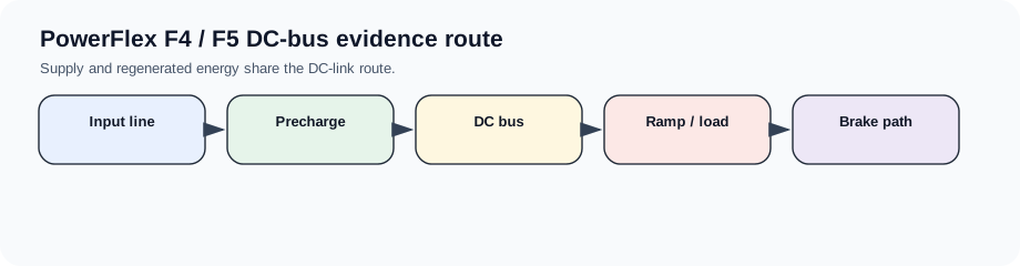
F5 is an energy-management question first
A PowerFlex F5 overvoltage event is usually useful only when paired with the machine condition. If it occurs during deceleration, lowering or a rapid stop, the first route is regenerated energy and the brake path. If it occurs during steady running or power-up, line voltage and transients become more important.
A page that says only “increase decel time” is incomplete. The repair decision depends on whether the application has a brake resistor, whether the chopper is operating, whether the resistor path is open or overloaded, and whether the DC bus measurement is credible.
F5 evidence order
Use the event timing to separate parameter/ramp correction from hardware repair.
F5 overvoltage split
| Event | First route | Hardware boundary |
|---|---|---|
| During deceleration | Ramp, inertia and regeneration | Brake resistor/chopper if fitted |
| During lowering or overhauling load | Mechanical energy into DC bus | Braking system and safety review |
| At power-up | Line voltage/transient | Input and bus sensing |
| After brake resistor change | Resistance, wiring and thermal protection | Chopper transistor/driver |
| Random under steady run | Line transients or bus feedback | DC-bus sensing and supply quality |
Close-out evidence
The close-out record should include the bus event, line voltage, decel demand, brake hardware, resistor measurement, duty cycle and whether the fault clears with a realistic machine profile rather than an unloaded bench run.
Field record checklist
- F5 timing
- Line voltage
- Decel profile
- Brake resistor/chopper evidence
- DC-bus trend
Technical basis and reference documents
This is an independent editorial technical reference. Original manufacturer documentation remains controlling for installation, repair and commissioning decisions.
OEM reference for PowerFlex installation and troubleshooting context.
Diagnostic workflow
Turn this record into a qualified service request
A repair decision is much more reliable when the request includes the exact identity of the drive, the first fault evidence and the machine condition when the symptom appeared.
- Complete drive type code / MLFB or nameplate model
- Fault code, fault value and first event before reset
- When the event appears: power-up, enable, ramp, run, decel or stop
- Motor/cable connected or isolated during the symptom
- Visible board, option-card, module and connector identifiers
- Previous repair history, replacement parts and repeat-failure pattern