
Scope of this technical record
Routes PowerFlex F4 undervoltage through plant supply sag, missing phase, input fuse/contactor, precharge and DC-bus evidence before a board conclusion.
Input and DC-link measurements require qualified procedure. Do not bypass interlocks or fuses to prove an undervoltage condition.
F4 undervoltage route
F4 starts at the drive input terminals and only moves inward after supply proof.
F4 undervoltage input path image
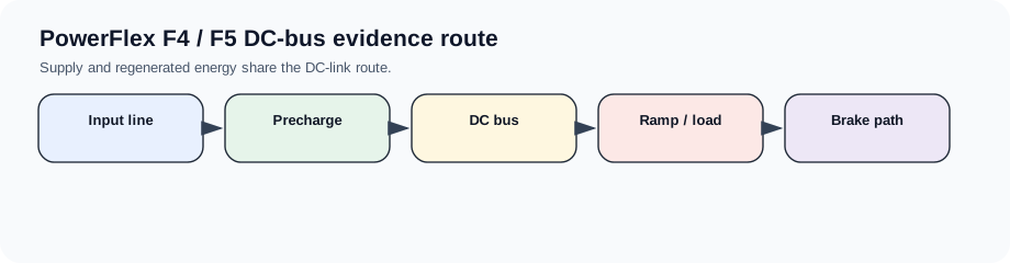
F4 starts outside the board
F4 often reflects DC-bus voltage below the drive threshold. The first evidence is therefore at the drive input terminals under real plant conditions, not at the control board. A weak supply, one missing phase, loose disconnect, contactor pole problem or plant sag can all look like an internal undervoltage case.
If the input evidence is stable, the route moves inward to precharge, rectifier and DC-link storage. The repair boundary should show why the external supply was cleared before internal hardware is suspected.
Undervoltage matrix
F4 evidence should preserve the timing: power-up, acceleration, steady run or plant-wide event.
F4 evidence split
| Timing | Likely boundary | Evidence |
|---|---|---|
| Power-up | Line/precharge | Input phases, fuses, precharge behaviour |
| During acceleration | Supply sag or weak line | Input voltage under load and line impedance |
| Random plant-wide | Utility/process disturbance | Other drives/events at same time |
| Only one machine | Disconnect/contactor/loose terminal | Thermal or vibration-sensitive connection |
| Input proven stable | Rectifier/precharge/DC link | Bus charge and internal supply evidence |
Repair request boundary
An internal repair request should include proof that line voltage and phase presence were measured at the drive, not only at the upstream panel. It should also state whether the drive display remained alive, whether other loads dipped, and whether F4 is paired with power-loss or bus-ripple evidence.
Field record checklist
- F4 timing
- Input voltage at drive
- Phase/fuse/contactor evidence
- Precharge/bus behaviour
- Plant disturbance context
Technical basis and reference documents
This is an independent editorial technical reference. Original manufacturer documentation remains controlling for installation, repair and commissioning decisions.
OEM source for PowerFlex safety and troubleshooting context.
Diagnostic workflow
Turn this record into a qualified service request
A repair decision is much more reliable when the request includes the exact identity of the drive, the first fault evidence and the machine condition when the symptom appeared.
- Complete drive type code / MLFB or nameplate model
- Fault code, fault value and first event before reset
- When the event appears: power-up, enable, ramp, run, decel or stop
- Motor/cable connected or isolated during the symptom
- Visible board, option-card, module and connector identifiers
- Previous repair history, replacement parts and repeat-failure pattern