
Scope of this technical record
Step-by-step route for 6SE70 KTY/PTC motor-temperature warnings, separating sensor-route faults from true motor overheating.
Do not bypass thermal protection. Any powered check must preserve motor and process safety.
6SE70 motor-temperature workflow route
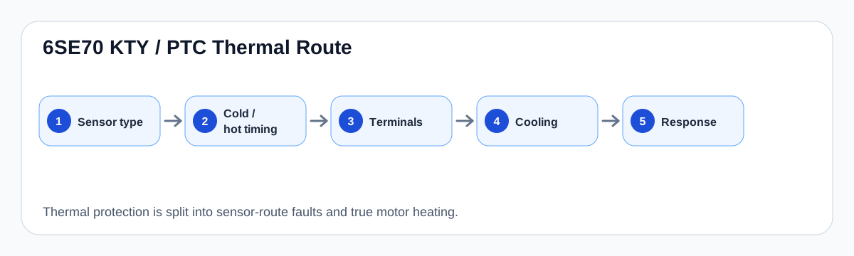
The workflow separates cold-start sensor faults from real load-related heating.
6SE70 motor-temperature workflow image
Workflow sequence
The workflow starts by identifying the sensor and classifying timing. Cold motor faults generally move toward wiring, terminals and configuration; load-related faults move toward fan, airflow, bearing, duty cycle and motor heating evidence.
After the physical sensor route is proven, configured warning/fault behaviour can be reviewed. Configuration is not a substitute for a working protective circuit.
Thermal diagnostic workflow
| Step | Evidence | Decision |
|---|---|---|
| 1 | KTY84 or PTC identified | Correct test method |
| 2 | Cold versus hot timing | Sensor route or true heating |
| 3 | Motor terminal and cable evidence | Wiring/connection boundary |
| 4 | Cooling and motor condition | Real overtemperature boundary |
| 5 | Configured response | Warning/trip handling after physical proof |
Field record checklist
- Sensor type
- Timing
- Terminal photos
- Continuity/resistance evidence where appropriate
- Cooling/fan state
- Configured response
Technical basis and reference documents
This is an independent editorial technical reference. Original manufacturer documentation remains controlling for installation, repair and commissioning decisions.
OEM basis for 6SE70 / 6SE71 safety, control connections, motor temperature evaluation and option context.
Internal technician note set used only to structure public diagnostic routes around KTY/PTC thermal protection and brake-control evidence.
Linked records
The fault boundary includes the motor thermal sensor, KTY84/PTC wiring, terminal expansion path and the parameterized response to warning or fault shutdown.
Routes KTY84 and PTC motor-temperature evidence through terminal input, expansion-board context and configured warning/fault response.
Turn this record into a qualified service request
A repair decision is much more reliable when the request includes the exact identity of the drive, the first fault evidence and the machine condition when the symptom appeared.
- Complete drive type code / MLFB or nameplate model
- Fault code, fault value and first event before reset
- When the event appears: power-up, enable, ramp, run, decel or stop
- Motor/cable connected or isolated during the symptom
- Visible board, option-card, module and connector identifiers
- Previous repair history, replacement parts and repeat-failure pattern