
Scope of this technical record
KTY84/PTC sensor path from motor terminal box through drive terminal/option interface to configured warning or trip response.
Sensor checks must preserve the protective function. Do not bridge or simulate a healthy sensor to keep production running without root-cause evidence.
6SE70 motor thermal sensor path
The path keeps KTY/PTC protection functional while the sensor route is checked.
6SE70 motor thermal sensor image
Path description
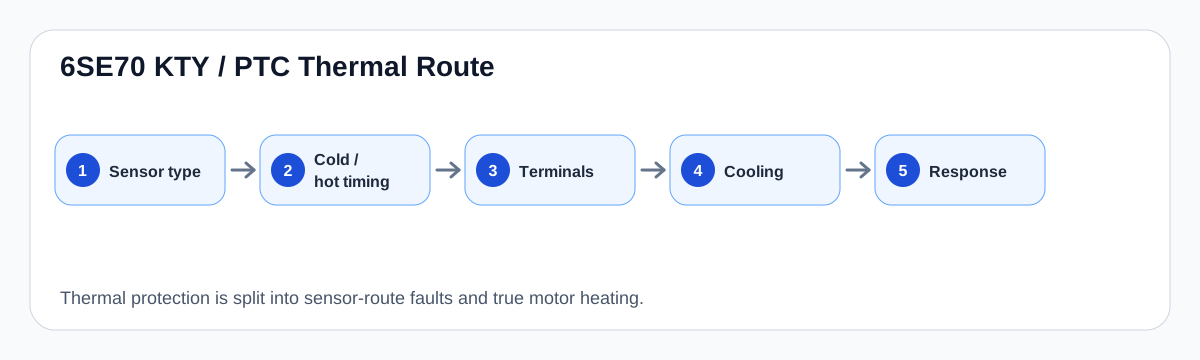
The thermal sensor path begins at the embedded motor sensor, passes through the motor terminal box and cable route, enters the drive terminal or expansion interface, then becomes a configured warning or trip response. Each node can create false or real thermal evidence.
A cold-start fault is usually a continuity/type/terminal question. A hot/load fault requires cooling evidence and motor condition before the drive input is blamed.
Field record checklist
- Sensor type
- Motor terminal continuity
- Cable and shield route
- Drive terminal identity
- Cold versus load timing
- Cooling evidence
Technical basis and reference documents
This is an independent editorial technical reference. Original manufacturer documentation remains controlling for installation, repair and commissioning decisions.
OEM basis for 6SE70 / 6SE71 safety, control connections, motor temperature evaluation and option context.
Internal technician note set used only to structure public diagnostic routes around KTY/PTC thermal protection and brake-control evidence.
Turn this record into a qualified service request
A repair decision is much more reliable when the request includes the exact identity of the drive, the first fault evidence and the machine condition when the symptom appeared.
- Complete drive type code / MLFB or nameplate model
- Fault code, fault value and first event before reset
- When the event appears: power-up, enable, ramp, run, decel or stop
- Motor/cable connected or isolated during the symptom
- Visible board, option-card, module and connector identifiers
- Previous repair history, replacement parts and repeat-failure pattern