
Scope of this technical record
KTY84/PTC motor-temperature warning or trip on SIMOVERT MASTERDRIVES 6SE70/6SE71 systems, separating true motor heating from sensor and terminal evidence.
Do not bypass motor thermal protection. Hot motors, cooling fans and process loads create mechanical and thermal hazards; inspect only under approved lockout and machine-safety procedure.
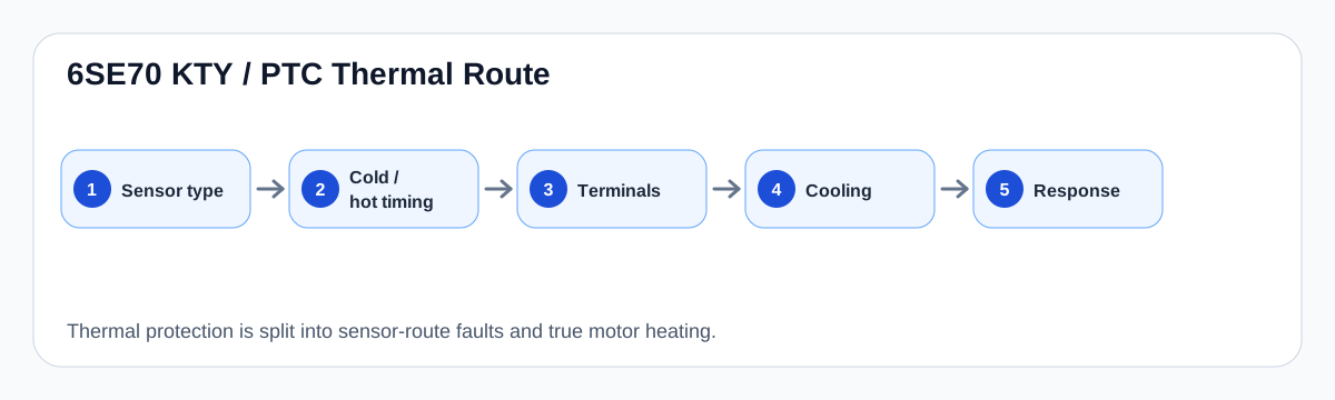
6SE70 KTY/PTC thermal route
Thermal trips are separated into sensor-route evidence and true motor heating before bypass or board replacement.
6SE70 KTY/PTC thermal evidence map
Why a thermal trip is not automatically a hot motor
MASTERDRIVES can evaluate motor temperature through KTY84 or PTC protection paths. A warning may be real overheating, but it may also be an open sensor circuit, wrong sensor type, terminal expansion issue, damaged cable, shielding/grounding problem or misconfigured warning/fault response.
The most useful split is cold-start versus load-related. A warning on a cold motor usually begins at wiring, sensor or parameter evidence. A warning after load or high ambient begins with cooling, motor fan, bearing, airflow and machine duty cycle.
KTY/PTC evidence split
| Timing | First boundary | Do not do |
|---|---|---|
| Cold-start warning | Sensor wiring / terminal / parameter | Bypass the sensor |
| After load | Cooling, fan, motor temperature | Assume the drive board failed |
| Intermittent with vibration | Cable/terminal connection | Change thermal thresholds first |
| After motor work | Sensor type and reconnection | Run before identity is confirmed |
Service record requirements
A credible request identifies the sensor type, terminal or option-board route, fault/warning timing, motor cooling condition and parameter response. Photos of the motor terminal box and drive-side terminal path are often more useful than a general cabinet photo.
Preserving the protection function is part of the repair. If a production line cannot run because of thermal protection, the responsible route is evidence capture and correction, not disabling the input.
Field record checklist
- KTY84 or PTC identity
- Cold/hot timing
- Motor terminal-box photo
- Drive terminal/option-board photo
- Cooling fan and airflow evidence
- Configured warning/fault response
Technical basis and reference documents
This is an independent editorial technical reference. Original manufacturer documentation remains controlling for installation, repair and commissioning decisions.
OEM basis for 6SE70 / 6SE71 safety, control connections, motor temperature evaluation and option context.
Internal technician note set used only to structure public diagnostic routes around KTY/PTC thermal protection and brake-control evidence.
Diagnostic workflow
Turn this record into a qualified service request
A repair decision is much more reliable when the request includes the exact identity of the drive, the first fault evidence and the machine condition when the symptom appeared.
- Complete drive type code / MLFB or nameplate model
- Fault code, fault value and first event before reset
- When the event appears: power-up, enable, ramp, run, decel or stop
- Motor/cable connected or isolated during the symptom
- Visible board, option-card, module and connector identifiers
- Previous repair history, replacement parts and repeat-failure pattern