
Scope of this technical record
Step-by-step route for VLT 2800 blinking-display and control-supply cases before keypad, control-board or replacement decisions.
Qualified electronics personnel only. Verify isolation and safe discharge before internal measurements.
Blinking-display workflow route
The workflow separates a keypad symptom from a weak control supply or downstream load.
VLT 2800 display workflow
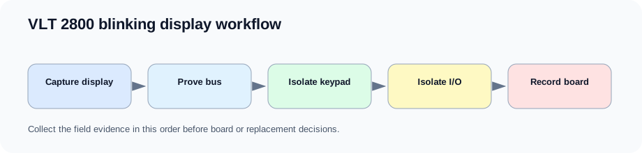
Workflow sequence
Begin with what the display does, then prove whether the drive has enough energy to boot. From there, isolate keypad and I/O loads before judging the board.
The route is useful because many compact-drive display symptoms are power-supply symptoms. A weak control rail can make a good keypad appear bad.
Workflow steps
| Step | Evidence | Decision |
|---|---|---|
| 1 | Record display pattern and power-up behavior | Decide whether fault-code routes are usable |
| 2 | Confirm input and DC-link behavior | Move to energy path if missing |
| 3 | Test keypad effect | Separate keypad from chassis |
| 4 | Isolate I/O and reference wiring | Find downstream rail load |
| 5 | Record CB1-CB3 and rail evidence | Repair or replacement decision |
Field record checklist
- Power-up video
- Input / DC-link values
- +5 V / +24 V status
- Keypad result
- I/O isolation
- Board label
Technical basis and reference documents
This is an independent editorial technical reference. Original manufacturer documentation remains controlling for installation, repair and commissioning decisions.
Confirms Alarm 13 overcurrent, Alarm 14 earth fault, Alarm 16 current short circuit, input-phase and DC-link alarm boundaries used to structure the first service routes.
Documents VLT 2800 warning and alarm text including Alarm 13 peak current, Alarm 14 ground fault, Alarm 15 switch-mode supply and Alarm 16 short-circuit cautions.
Provides practical Alarm 14 separation between motor/cabling evidence and drive-side current-sensor evidence, including no-motor current observations and manual-initialization caution.
Linked records
A blinking display is a control-power evidence problem. The useful route is line input, DC link, auxiliary supply start-up, +5 V / +24 V rail stability, keypad load, I/O load and control-board boundary. It should not be handled as a simple panel replacement until the chassis-side electronics are proven stable.
The public manual and fault-code pages define the alarm as low intermediate-circuit voltage; the database route separates line supply, DC-link energy and control-card behavior before a repair decision.
Low-voltage route for VLT 2800 blinking-display and control-board cases: DC-link feed, auxiliary supply start-up, +5 V logic, +24 V control, 10 V reference, keypad interface and external I/O load must be separated.
Energy path for compact Danfoss cases where DC-link undervoltage, display instability or power-board suspicion must be separated from input fuses, rectifier, DC link and auxiliary supply behavior.
Turn this record into a qualified service request
A repair decision is much more reliable when the request includes the exact identity of the drive, the first fault evidence and the machine condition when the symptom appeared.
- Complete drive type code / MLFB or nameplate model
- Fault code, fault value and first event before reset
- When the event appears: power-up, enable, ramp, run, decel or stop
- Motor/cable connected or isolated during the symptom
- Visible board, option-card, module and connector identifiers
- Previous repair history, replacement parts and repeat-failure pattern