
Scope of this technical record
Control-board low-voltage path for blinking display, I/O load and reference-supply cases on VLT 2800 compact drives.
Qualified personnel only. Low-voltage rails are still connected to hazardous drive electronics; isolate and use proper measurement practice.
VLT 2800 low-voltage control route
The path finds whether low-voltage rails collapse from supply failure or external loads.
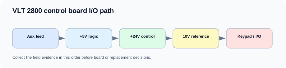
VLT 2800 control-board I/O path
What the low-voltage path proves
The path begins with DC-link-derived auxiliary supply and ends at display, I/O and reference loads. If the rail collapses only when field wiring is attached, the board may be protecting itself from an external load.
The useful record is a rail stability comparison with keypad and I/O loads connected and disconnected. That turns a blinking-display complaint into actionable evidence.
Low-voltage path
| Node | Service evidence | Typical decision |
|---|---|---|
| Auxiliary supply input | DC-link present | Energy path or control path |
| +5 V rail | Logic boot stable or pulsing | CPU/display supply boundary |
| +24 V rail | Control output load | I/O wiring or board load |
| 10 V reference | Overloaded reference | External analog wiring |
| Keypad interface | Display follows keypad or chassis | Keypad versus control board |
Field record checklist
- DC-link present
- +5 V
- +24 V
- 10 V reference
- Keypad test
- I/O isolation
- Board label
Technical basis and reference documents
This is an independent editorial technical reference. Original manufacturer documentation remains controlling for installation, repair and commissioning decisions.
Confirms Alarm 13 overcurrent, Alarm 14 earth fault, Alarm 16 current short circuit, input-phase and DC-link alarm boundaries used to structure the first service routes.
Documents VLT 2800 warning and alarm text including Alarm 13 peak current, Alarm 14 ground fault, Alarm 15 switch-mode supply and Alarm 16 short-circuit cautions.
Provides practical Alarm 14 separation between motor/cabling evidence and drive-side current-sensor evidence, including no-motor current observations and manual-initialization caution.
Turn this record into a qualified service request
A repair decision is much more reliable when the request includes the exact identity of the drive, the first fault evidence and the machine condition when the symptom appeared.
- Complete drive type code / MLFB or nameplate model
- Fault code, fault value and first event before reset
- When the event appears: power-up, enable, ramp, run, decel or stop
- Motor/cable connected or isolated during the symptom
- Visible board, option-card, module and connector identifiers
- Previous repair history, replacement parts and repeat-failure pattern