
Scope of this technical record
Workflow for Danfoss VLT Alarm 29 cases where the technician must separate real thermal overload, fan or airflow maintenance, cabinet derating and temperature-feedback electronics before replacing a board or full drive.
Do not defeat thermal protection. Secure the process before stopping ventilation or opening the panel. Fans may restart and heatsinks can remain hot. Internal inspection requires isolation and DC-link discharge verification.
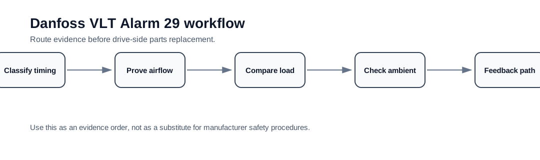
Danfoss Alarm 29 workflow route
The workflow distinguishes real overheating from cold-start feedback faults.
Danfoss Alarm 29 workflow image
Workflow outcome
The workflow should classify the case as cooling maintenance, cabinet/environment correction, load/derating correction, fan/fan-supply repair, temperature-feedback investigation or replacement planning after thermal damage. Each outcome needs different evidence and different urgency.
Step 1 — split cold-start from hot-load Alarm 29
If Alarm 29 appears when the drive is physically cold, document that immediately. Cold-start Alarm 29 is not the same as a drive that overheats after an hour of high load. It moves faster toward feedback, sensor or control electronics, after the fan and airflow route is confirmed.
Step 2 — prove the cooling path
Inspect fan operation, blocked filters, heatsink dust, top/bottom clearance, cabinet ventilation and recirculated hot air. A high-quality support request includes photos before cleaning, not only after the machine is returned to service.
Alarm 29 workflow evidence
| Finding | Likely route | Next action |
|---|---|---|
| Fan stopped, noisy or obstructed | Fan/fan-supply route | Correct fan path and retest under controlled load |
| Dust or blocked fins | Maintenance route | Clean, record before/after and check recurrence |
| High cabinet ambient | Installation / ventilation route | Correct cooling, derating or panel airflow |
| Trip only at high load | Load/derating route | Compare output current, duty and drive rating |
| Trip cold with cooling route normal | Temperature-feedback / control route | Build sensor/board evidence package |
Step 3 — decide whether the drive is repairable
If the alarm followed a real overheating event, inspect for collateral signs: fan failure, melted ducting, discoloured board areas, capacitor heat stress and previous thermal repairs. If the alarm is false or cold, collect temperature feedback and board identity evidence. The replacement decision depends on frame size, parts availability and whether the thermal root cause was solved.
Field record checklist
- Cold/hot trip classification
- Fan operation evidence
- Heatsink and filter photos
- Cabinet temperature and airflow path
- Load current and duty cycle
- Sensor/board evidence if physical cooling is normal
Technical basis and reference documents
This is an independent editorial technical reference. Original manufacturer documentation remains controlling for installation, repair and commissioning decisions.
Used to anchor Alarm 4 as a mains phase-loss check, Alarm 29 as a drive over-temperature check and DC-link overvoltage as a supply/regeneration/brake-path issue.
Used to keep Alarm 29 diagnosis focused on real heatsink temperature, airflow, fan condition, ambient temperature and load before sensor or board conclusions.
Used as public VLT-family context for heatsink temperature alarm wording, high-voltage safety and FC-family drive service boundaries.
Linked records
The drive heatsink temperature has exceeded the allowed limit or the temperature feedback/cooling path is not credible.
Routes alarm 29 through cooling fans, heatsink contamination, airflow, cabinet ventilation, ambient temperature, load current and temperature feedback.
Turn this record into a qualified service request
A repair decision is much more reliable when the request includes the exact identity of the drive, the first fault evidence and the machine condition when the symptom appeared.
- Complete drive type code / MLFB or nameplate model
- Fault code, fault value and first event before reset
- When the event appears: power-up, enable, ramp, run, decel or stop
- Motor/cable connected or isolated during the symptom
- Visible board, option-card, module and connector identifiers
- Previous repair history, replacement parts and repeat-failure pattern