
Scope of this technical record
Danfoss VLT Alarm 29 heatsink-temperature route for deciding whether the trip is caused by blocked airflow, fan failure, contaminated heatsink, high ambient, cabinet ventilation, overload/derating, long thermal duty or temperature-feedback electronics.
Do not bypass thermal protection or keep a drive running with confirmed over-temperature. Fans may start unexpectedly and heatsinks may remain hot after shutdown. Verify isolation and DC-link discharge before internal cleaning or inspection.
Danfoss Alarm 29 thermal route
Alarm 29 is routed through physical cooling and load evidence before sensor or board conclusions.
Danfoss Alarm 29 heatsink image
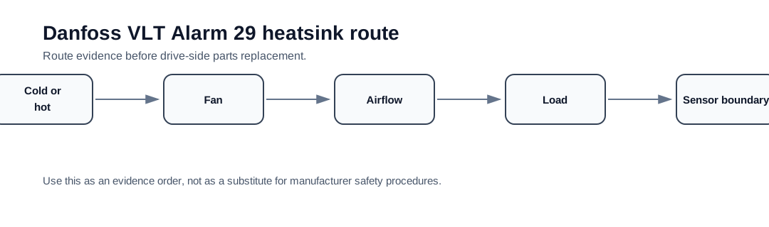
Alarm 29 is a thermal route before it is a board route
Danfoss support material describes Alarm 29 as a heatsink temperature condition. The first route is therefore physical cooling: fan operation, airflow, filters, heatsink fins, cabinet clearance, ambient temperature and load. A power board or temperature-sensor suspicion becomes credible only after the cooling route and load conditions are documented.
The first split is hot-load versus cold-start. A trip after running under load points toward thermal stress, blocked airflow or derating. A trip at cold power-up with no true heat source points toward temperature feedback, sensor path or control electronics. Treating both cases as the same fan fault misses the repair boundary.
Cold trip versus hot trip
A hot trip should preserve load current, run time, ambient, cabinet temperature and airflow evidence. A cold trip should preserve the heatsink temperature condition, fan state and whether the measured/indicated temperature is credible. This split is more useful than simply clearing the alarm and waiting for the drive to cool.
Alarm 29 decision matrix
| Observed pattern | First boundary | Evidence to collect |
|---|---|---|
| Trips after long load run | Real overheating / derating | Load current, duty cycle, ambient and heatsink condition |
| Trips in hot enclosure | Cabinet ventilation | Panel temperature, clearances, filter condition and airflow path |
| Fan not running or noisy | Cooling fan / fan supply | Fan state, obstruction, replacement history and connector evidence |
| Heatsink packed with dust | Maintenance / contamination | Before-cleaning photos and thermal recurrence history |
| Alarm 29 at cold power-up | Temperature feedback or control electronics | Cold-state evidence, sensor route and board photos after isolation |
When Alarm 29 requires repair support
Repair support becomes relevant when the drive trips cold, the fan path is proven but the alarm persists, the heatsink sensor evidence is implausible, or a thermal event has damaged the power stage. The support package should not only show the code; it should show why the cooling route was not enough to explain the alarm.
- Record whether the drive is cold or hot when Alarm 29 appears
- Photograph the fan, heatsink fins, filters, ducting and cabinet layout
- Record output current, duty cycle and ambient temperature
- Check for blocked airflow above and below the drive
- Escalate to sensor/control electronics only after physical cooling is proven
Field record checklist
- Full VLT type code and frame
- Cold or hot trip timing
- Fan operation and airflow evidence
- Heatsink/filter/cabinet photos
- Load current and duty cycle
- Temperature feedback evidence if escalated
Technical basis and reference documents
This is an independent editorial technical reference. Original manufacturer documentation remains controlling for installation, repair and commissioning decisions.
Used to anchor Alarm 4 as a mains phase-loss check, Alarm 29 as a drive over-temperature check and DC-link overvoltage as a supply/regeneration/brake-path issue.
Used to keep Alarm 29 diagnosis focused on real heatsink temperature, airflow, fan condition, ambient temperature and load before sensor or board conclusions.
Used as public VLT-family context for heatsink temperature alarm wording, high-voltage safety and FC-family drive service boundaries.
Diagnostic workflow
Turn this record into a qualified service request
A repair decision is much more reliable when the request includes the exact identity of the drive, the first fault evidence and the machine condition when the symptom appeared.
- Complete drive type code / MLFB or nameplate model
- Fault code, fault value and first event before reset
- When the event appears: power-up, enable, ramp, run, decel or stop
- Motor/cable connected or isolated during the symptom
- Visible board, option-card, module and connector identifiers
- Previous repair history, replacement parts and repeat-failure pattern