
Scope of this technical record
Danfoss VLT cooling and heatsink path for connecting Alarm 29 evidence to cabinet airflow, fan operation, heatsink contamination, temperature feedback, load current and thermal protection logic.
Thermal protection protects the drive and machine from destructive overheating. Do not bypass fans, sensors or alarm response. Internal cleaning and inspection require qualified isolation, discharge verification and appropriate contamination control.
Danfoss cooling / heatsink route
The cooling path is treated as a system, not as a single fan replacement.
Danfoss cooling and heatsink path image
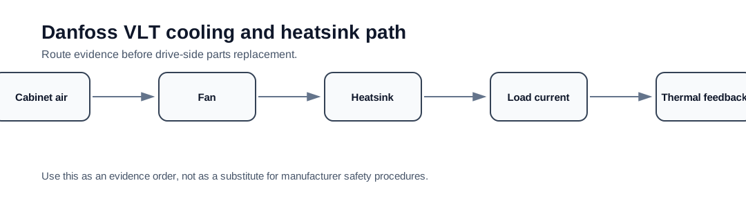
The cooling path is a system, not one fan
A heatsink-temperature alarm is produced by a system: ambient air enters the cabinet, flows through or around the drive, the fan moves air across fins, the heatsink transfers losses from power semiconductors, and the temperature feedback reports whether the thermal state is safe. Any weak link can create Alarm 29.
This page exists because support requests often reduce thermal problems to a single part. A failed fan is common, but blocked filters, bad cabinet design, high ambient, excessive load current, long duty cycle, contaminated fins or false temperature feedback can all produce the same alarm label.
Cooling-path evidence map
Document airflow before disassembly. Photos of the fan, heatsink fins, filters, top and bottom clearance, neighboring heat sources and cabinet ventilation are often more useful than a close-up of the keypad. For cold-start alarms, add temperature feedback and board-route evidence after safe isolation.
Cooling path to repair decision
| Path area | What it proves | Repair meaning |
|---|---|---|
| Cabinet intake/exhaust | Whether the drive receives usable cooling air | Panel ventilation or installation correction |
| Drive fan | Whether forced airflow exists | Fan/fan-supply inspection or replacement |
| Heatsink fins | Whether heat transfer is blocked | Maintenance/cleaning and recurrence monitoring |
| Load current / duty | Whether the drive is thermally overloaded | Derating, process correction or larger drive |
| Temperature feedback | Whether the alarm is credible when cold | Sensor/control electronics investigation |
Support evidence request
A cooling/heatsink support request should include the exact type code, first Alarm 29 timing, fan condition, photos of heatsink and filters, cabinet ambient, output current and any recent fan or cleaning history. If the alarm is cold and the cooling path is clean, include internal board and sensor-route photos after qualified isolation.
Field record checklist
- Fan and heatsink photos before cleaning
- Cabinet airflow and ambient evidence
- Load current and derating condition
- Cold versus hot trip classification
- Fan replacement or maintenance history
- Sensor/control evidence if escalated
Technical basis and reference documents
This is an independent editorial technical reference. Original manufacturer documentation remains controlling for installation, repair and commissioning decisions.
Used to anchor Alarm 4 as a mains phase-loss check, Alarm 29 as a drive over-temperature check and DC-link overvoltage as a supply/regeneration/brake-path issue.
Used to keep Alarm 29 diagnosis focused on real heatsink temperature, airflow, fan condition, ambient temperature and load before sensor or board conclusions.
Used as public VLT-family context for heatsink temperature alarm wording, high-voltage safety and FC-family drive service boundaries.
Turn this record into a qualified service request
A repair decision is much more reliable when the request includes the exact identity of the drive, the first fault evidence and the machine condition when the symptom appeared.
- Complete drive type code / MLFB or nameplate model
- Fault code, fault value and first event before reset
- When the event appears: power-up, enable, ramp, run, decel or stop
- Motor/cable connected or isolated during the symptom
- Visible board, option-card, module and connector identifiers
- Previous repair history, replacement parts and repeat-failure pattern