
Scope of this technical record
Brake release, brake close, load slip or trip symptoms on 6SE70/6SE71 crane, hoist, lift and vertical-axis applications.
Brake-control work can create uncontrolled motion. Mechanically secure the load and use approved site procedure before checking outputs or changing timing parameters.
6SE70 brake-control route
Brake symptoms are routed as a machine-safety sequence, not just an output relay fault.
6SE70 brake-control evidence map
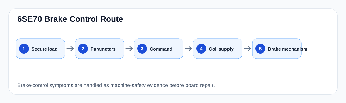
Brake control is a machine-safety route
MASTERDRIVES brake control can act on a motor-mounted brake or external brake, with release and close timing/thresholds configured in the drive. The brake is therefore not simply a relay output: it is a timed interaction between torque build-up, coil supply, mechanical brake condition and load direction.
A fault after a brake change, contactor change or parameter edit must be investigated as a sequence. The drive may command correctly while the coil supply, brake air gap, wear state or feedback/interlock causes the machine symptom.
Brake-control evidence sequence
| Evidence | Question | Risk if skipped |
|---|---|---|
| Load secured | Can the axis be tested safely? | Uncontrolled movement |
| Parameter snapshot | What were release/close delays and thresholds? | No baseline after edits |
| Command output | Does the drive command brake release/close? | Wrong board or relay claim |
| Coil supply | Is correct voltage reaching the brake? | Parameter tuning for wiring failure |
| Mechanical brake | Does the brake physically release and hold? | Electrical repair for worn brake |
Field-to-board boundary
Only after load safety, timing parameters, coil supply and mechanical brake condition are documented should the interface/terminal board route be used. A repair shop cannot safely evaluate a brake-output complaint without knowing whether the machine brake itself is healthy.
For cranes, hoists and vertical axes, the support request should include load direction, brake voltage, release/close behaviour, any feedback/interlock and whether the symptom occurs on start, stop, inching or emergency stop.
Field record checklist
- Machine type and load direction
- Brake voltage and wiring
- Parameter snapshot
- Drive output evidence
- Coil supply evidence
- Mechanical brake inspection
- Feedback/interlock status
Technical basis and reference documents
This is an independent editorial technical reference. Original manufacturer documentation remains controlling for installation, repair and commissioning decisions.
OEM basis for 6SE70 / 6SE71 safety, control connections, motor temperature evaluation and option context.
Internal technician note set used only to structure public diagnostic routes around KTY/PTC thermal protection and brake-control evidence.
Diagnostic workflow
Turn this record into a qualified service request
A repair decision is much more reliable when the request includes the exact identity of the drive, the first fault evidence and the machine condition when the symptom appeared.
- Complete drive type code / MLFB or nameplate model
- Fault code, fault value and first event before reset
- When the event appears: power-up, enable, ramp, run, decel or stop
- Motor/cable connected or isolated during the symptom
- Visible board, option-card, module and connector identifiers
- Previous repair history, replacement parts and repeat-failure pattern