
Scope of this technical record
ATV61 / ATV71 USF route for users deciding whether an undervoltage fault comes from incoming supply, fuses, contactor timing, line sag, precharge, DC-link charging, undervoltage-management settings or internal measurement hardware.
USF does not prove the drive is safe to touch. The DC bus can remain charged after an undervoltage event. Follow lockout, verify discharge and use qualified measurement procedure before input, precharge or DC-link inspection.
USF DC-link undervoltage route
USF starts with measured input and charging evidence before any control-board conclusion.
ATV61 / ATV71 USF undervoltage evidence image
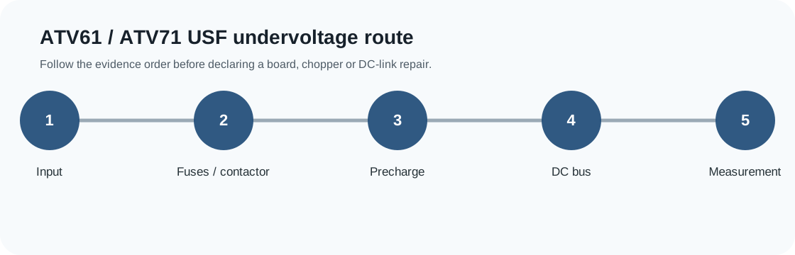
USF service decision matrix
USF needs a low-bus split before a board decision: incoming line, contactor/fuse, precharge, DC-link storage or bus measurement.
| Observed situation | Decision needed | Evidence to collect |
|---|---|---|
| USF at power-up | Input/precharge boundary | L1/L2/L3, fuses, contactor and bus-rise evidence |
| USF under load | Supply sag or line path | Voltage under load and upstream event timing |
| USF with stable input | Internal charge or measurement path | Precharge, rectifier, capacitor and bus feedback evidence |
USF begins with measured energy, not guesswork
USF indicates that the ATV61 / ATV71 DC bus has fallen below the undervoltage boundary. Schneider guidance points the technician to incoming line measurements, mains-voltage monitoring and DC-bus measurement. That means the first page objective is to prove whether the problem is outside the drive, in the charging path, or in internal sensing.
Many USF cases are field problems: weak supply, a contactor dropping out, a fuse or disconnect issue, line sag when another load starts, or a voltage-class/parameter mismatch. The drive electronics become suspect only after the input and DC-link evidence is coherent.
Separate power-up USF from running USF
A power-up USF and a running-load USF do not have the same first boundary. Power-up USF points toward the input path, contactor, fuses, precharge sequence and DC-link charge. Running USF points toward supply sag, upstream protection, line contactor behavior or load-related bus collapse. Intermittent USF may require event timing, plant-load correlation and terminal inspection rather than an immediate board decision.
USF timing map
| USF timing | Likely first boundary | Evidence to collect |
|---|---|---|
| At power-up | Input path and precharge | L1/L2/L3 at drive, fuse/contactor state, bus rise |
| After run command | Supply sag under load | Line voltage under load, current demand, upstream contactor/fuse condition |
| After line contactor transition | Undervoltage timeout and contactor timing | Contactor timing, menu monitoring, event order |
| Intermittent plant-wide | Incoming utility or generator instability | Voltage trend, other load events, transformer tap condition |
| After previous repair | Charging or sensing path | Precharge evidence, DC-link measurement point, repair history |
Measurements that make a USF case actionable
A useful USF request states where the voltage was measured. Upstream panel voltage alone is not enough. The drive terminals may see a different condition because of fuses, disconnects, contactor poles, wiring heat, line reactors or loose terminals. The DC bus measurement must also be collected only under a qualified safe procedure.
Thresholds and undervoltage timing can be parameterized in the fault-management area, but parameters should not be used to hide a real power problem. A timeout change can be appropriate for contactor sequencing; it is not a substitute for proving the line supply and charging path.
- Measure L1-L2, L2-L3 and L1-L3 at the drive terminals under the relevant condition
- Compare measured line voltage with the drive voltage class and monitoring menu reading
- Record DC-bus voltage at PA(+)/PC(-) only when the procedure is qualified and safe
- Inspect fuses, disconnect, contactor poles, wiring heat and loose terminals
- Record whether USF follows plant load starts, generator transfer or contactor sequencing
When USF becomes a drive-side repair case
If the incoming line is stable at the drive terminals and USF remains repeatable, the investigation moves inward: precharge path, rectifier, DC-link capacitors, bus feedback, measurement scaling and auxiliary supply interaction. That is a different evidence package from an output-stage fault and should not be routed to an IGBT replacement by default.
The strongest support request includes type code, voltage class, first fault, line measurements, DC-bus evidence, contactor/fuse photos and a short description of the machine state. With those facts, the next step can be field correction, precharge/DC-link repair, control measurement investigation or replacement planning.
Field record checklist
- USF timing
- Line measurements at drive terminals
- DC-bus evidence
- Fuse/contactor/precharge evidence
- Menu monitoring comparison
- Plant-load correlation
Technical basis and reference documents
This is an independent editorial technical reference. Original manufacturer documentation remains controlling for installation, repair and commissioning decisions.
Used to anchor OSF around DC-bus over-supply detection during capacitor charging and PWM-deactivated states.
Used to anchor USF around low DC-bus voltage and field measurements on L1/L2/L3 and PA(+)/PC(-).
Used to anchor undervoltage thresholds, incoming line checks, monitoring menu comparison and undervoltage-management timing.
Used for family-level fault-management and drive-parameter context; public pages avoid reproducing proprietary tables.
Diagnostic workflow
Turn this record into a qualified service request
A repair decision is much more reliable when the request includes the exact identity of the drive, the first fault evidence and the machine condition when the symptom appeared.
- Complete drive type code / MLFB or nameplate model
- Fault code, fault value and first event before reset
- When the event appears: power-up, enable, ramp, run, decel or stop
- Motor/cable connected or isolated during the symptom
- Visible board, option-card, module and connector identifiers
- Previous repair history, replacement parts and repeat-failure pattern