
Scope of this technical record
ATV61 / ATV71 SCF short-circuit route for users deciding whether the trip is motor cable, motor insulation, output terminals, output-connected equipment, transistor-test evidence, gate-driver or power-bridge failure.
Treat SCF as a stop-condition fault. Do not repeatedly reset into SCF, do not insulation-test through the connected drive, and do not power a repaired bridge until motor/cable and driver evidence are credible.
SCF stop-condition route
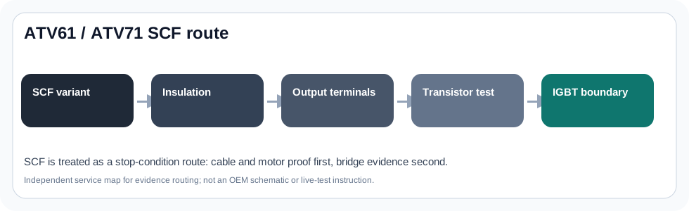
SCF is treated as destructive until motor, cable and terminal evidence justify drive-side escalation.
ATV61 / ATV71 SCF short-circuit image
Service decision matrix
SCF is a stop-condition route. The page shows what must be proven before another power-up or power-stage repair.
| Observed situation | Decision needed | Evidence to collect |
|---|---|---|
| Immediate SCF | External short or bridge fault | Motor/cable insulation and terminal condition |
| SCF with moisture pattern | Cable/motor installation | Terminal box, glands and environmental evidence |
| SCF after module repair | Driver/root-cause failure | Gate-driver, current feedback and external proof |
SCF is handled more conservatively than OCF
SCF is a short-circuit protection family. In Schneider's public guidance, SCF1 points to short-circuit or grounding at the drive output, and the recommended route includes checking motor cables, testing motor and leads with the correct isolation discipline, checking wiring tightness and using the drive's transistor-test path where applicable.
That means the page must answer a practical stop/continue question. Is there a short or leakage path outside the drive, or is the drive's output bridge, current detection or gate-driver boundary now suspect? Until the output path is proven, repeated powered tests are not a diagnostic method; they are a failure multiplier.
SCF pattern split
Do not collapse every SCF into one component. The first distinction is whether the fault follows the motor/cable/output accessories or remains with the drive when the external path is safely removed from suspicion.
SCF evidence matrix
| Pattern | First boundary | Repair decision impact |
|---|---|---|
| SCF / SCF1 immediately on enable | Cable, motor, terminals, output bridge | Do not quote board repair until external short evidence is documented |
| Fault after rain, washdown or high humidity | Motor terminal box, cable glands, contamination | Correct installation/environment before condemning drive |
| Fault after output contactor or cable movement | Output hardware and loose strands | Inspect external switching and terminals before drive-side checks |
| Fault remains after qualified external isolation | IGBT bridge, driver, current feedback | Prepare controlled repair evidence and avoid repeated full-power starts |
| Fault appears after IGBT replacement | Driver channel, protection feedback, unresolved field fault | Another module is a stop condition until root cause is proven |
Motor and cable proof before transistor-test conclusions
The useful motor/cable evidence is not a vague statement that the motor looks fine. It includes insulation readings taken with the drive isolated, terminal-box condition, cable route and bending points, cable shield/PE handling, any output contactor or filter, and whether the fault changes with the motor disconnected under a qualified procedure.
Transistor-test results are most useful after the output path has been documented. If the test points to a phase or bridge condition while the motor/cable evidence is clean, the case moves to the power-stage evidence record. If the external path is not clean, a power-board replacement may only hide the actual cause until the next start.
Drive-side escalation boundary
Once the external short path is not credible, the drive-side route should still be staged. Static phase checks, DC-bus condition, gate-driver supply, driver channel comparison, current-feedback plausibility and previous repair history all matter before power is applied to a repaired bridge.
For high-power frames, photographs of board labels, output module labels and the exact failure marks are more useful than a generic “module bad” description. The goal is to prevent the next module from becoming the diagnostic tool.
Support request checklist for SCF
A good SCF request is conservative. It documents the output path, prevents unsafe retesting and shows why the drive is now suspect, if it is suspect at all.
- Exact SCF variant if displayed and first-fault order
- Motor/cable insulation evidence and terminal photos
- Output contactor/filter/capacitor details if present
- Result with motor/output isolated only under qualified procedure
- Transistor/static check notes if performed by qualified personnel
- Previous IGBT, gate-driver or power-board replacement history
Field record checklist
- SCF variant and timing
- Motor/cable insulation proof
- Output terminal/accessory evidence
- Transistor/static output evidence
- Gate-driver/current-feedback suspicion
- Pre-power stop conditions
Technical basis and reference documents
This is an independent editorial technical reference. Original manufacturer documentation remains controlling for installation, repair and commissioning decisions.
Used to anchor OCF around hardware current limitation, motor data, high inertia, excessive load and mechanical blockage.
Used to anchor SCF1 around drive output short/grounding, motor cable checks, motor insulation and transistor test routing.
OEM programming and fault-reference context for Altivar 71 diagnostic pages.
OEM installation and wiring context for safe output and motor-cable evidence collection.
Diagnostic workflow
Turn this record into a qualified service request
A repair decision is much more reliable when the request includes the exact identity of the drive, the first fault evidence and the machine condition when the symptom appeared.
- Complete drive type code / MLFB or nameplate model
- Fault code, fault value and first event before reset
- When the event appears: power-up, enable, ramp, run, decel or stop
- Motor/cable connected or isolated during the symptom
- Visible board, option-card, module and connector identifiers
- Previous repair history, replacement parts and repeat-failure pattern