
Scope of this technical record
ATV61 / ATV71 OSF route for users deciding whether an overvoltage trip comes from high line voltage, capacitor charging, regenerative deceleration, braking resistor/chopper condition, common DC-bus influence or a DC-link measurement problem.
OSF is a high-energy DC-link event. Do not work inside the drive until the supply is isolated and DC-bus discharge has been verified with a suitable meter. Do not bypass brake protection or repeatedly test a regenerative load without a controlled procedure.
OSF DC-link overvoltage route
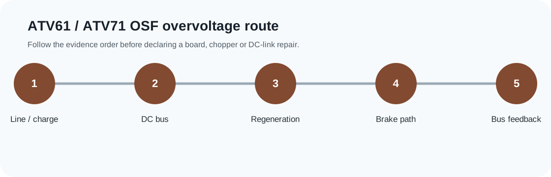
OSF is routed through line and machine energy before chopper, feedback or board repair conclusions.
ATV61 / ATV71 OSF overvoltage evidence image
OSF service decision matrix
OSF needs a high-bus split before a part decision: line/charging, regenerated energy, brake path or internal bus-feedback evidence.
| Observed situation | Decision needed | Evidence to collect |
|---|---|---|
| OSF at power-up | Line or charging condition | Drive-terminal line voltage and bus-rise evidence |
| OSF during deceleration | Regeneration or brake path | Ramp, load inertia, resistor/chopper proof |
| OSF after repair | Unresolved bus feedback or energy path | Repair history and DC-link measurement evidence |
OSF is an energy-management fault before it is a board fault
OSF on an ATV61 or ATV71 is not a generic alarm that automatically points to the control board. It means the drive has detected an over-supply or overvoltage condition on the DC-bus route. The case may begin at the incoming line, at the capacitor charging state, or at the load returning energy into the DC link during deceleration.
The practical question is where the energy came from. If OSF appears when the machine stops, the likely first boundary is ramp time, load inertia, hoisting or overhauling load behavior, braking resistor suitability and brake-chopper evidence. If OSF appears at power-up or while idle, the first boundary is line voltage and DC-link detection rather than braking hardware.
Classify OSF by timing before touching hardware
The first useful field note is the exact event timing. A trip during capacitor charging is not diagnosed like a trip at the end of a fast deceleration. A trip in a facility with unstable generator power is not the same as a trip on a crane lowering cycle. Each timing route has a different first measurement.
OSF timing map
| OSF timing | Likely first boundary | Evidence to collect |
|---|---|---|
| Power-up / charging | Line supply and bus-charge threshold | L1/L2/L3 at drive, voltage class, bus rise observation |
| Idle or PWM disabled | High line or bus-sensing state | Line voltage trend, DC-bus reading, incoming transformer tap condition |
| During deceleration | Regenerative load and ramp | Decel time, machine inertia, load direction, stop command timing |
| Only with braking resistor connected | Brake path and duty | Resistor ohms/rating, wiring, chopper setting, heat pattern |
| After previous repair | Measurement or unresolved energy path | Repair history, bus sensing evidence, brake/line evidence |
Braking path checks that prevent wrong conclusions
A deceleration OSF is usually checked by users who want to know whether to increase decel time, add a braking resistor, replace the brake chopper, or repair the drive. The correct answer depends on the energy route. A high-inertia fan, centrifuge, winder or hoist can push bus voltage up even when the drive electronics are healthy.
The braking evidence must include the actual resistor installation where fitted: resistance value, power rating, wiring route, thermal protection, duty cycle and whether the chopper command is plausible. A burned resistor, open thermal switch, wrong resistor value or unsupported load cycle can make a healthy drive trip on OSF.
- Record whether the load is overhauling, high-inertia or vertical
- Compare deceleration time with the mechanical energy being returned
- Inspect resistor value, power rating, wiring and thermal contact condition
- Check whether OSF changes with a safe ramp-time change
- Do not assume a board failure until line and braking evidence are reconciled
When OSF becomes an internal repair case
OSF becomes a drive-side repair case only after line voltage, machine energy and braking hardware no longer explain the DC-bus rise. At that point the evidence should move inward to DC-link measurement, bus feedback, brake-chopper command and power-board condition. That escalation requires careful discharge verification and qualified measurement practices.
A replacement request should not say only “ATV71 OSF, need board.” It should show the type code, voltage class, trip timing, line voltage at the drive terminals, DC-bus reading where safely available, resistor evidence, ramp/load condition and previous repair history.
Field record checklist
- OSF timing
- Line voltage at drive terminals
- DC-bus reading where qualified
- Deceleration and load evidence
- Braking resistor/chopper evidence
- Previous repair history
Technical basis and reference documents
This is an independent editorial technical reference. Original manufacturer documentation remains controlling for installation, repair and commissioning decisions.
Used to anchor OSF around DC-bus over-supply detection during capacitor charging and PWM-deactivated states.
Used to anchor USF around low DC-bus voltage and field measurements on L1/L2/L3 and PA(+)/PC(-).
Used to anchor undervoltage thresholds, incoming line checks, monitoring menu comparison and undervoltage-management timing.
Used for family-level fault-management and drive-parameter context; public pages avoid reproducing proprietary tables.
Diagnostic workflow
Turn this record into a qualified service request
A repair decision is much more reliable when the request includes the exact identity of the drive, the first fault evidence and the machine condition when the symptom appeared.
- Complete drive type code / MLFB or nameplate model
- Fault code, fault value and first event before reset
- When the event appears: power-up, enable, ramp, run, decel or stop
- Motor/cable connected or isolated during the symptom
- Visible board, option-card, module and connector identifiers
- Previous repair history, replacement parts and repeat-failure pattern