
Scope of this technical record
Alarm 16 short-circuit route for VLT 2800 / 2900 cases where output terminals, cable, motor and gate-driver evidence must be separated before another power test.
Alarm 16 is a stop condition. Do not reset and re-run until the short-circuit boundary has been found and the output stage is safe to energize.
VLT 2800 Alarm 16 route
Alarm 16 is a stop condition until the short-circuit boundary is known.
VLT 2800 Alarm 16 route
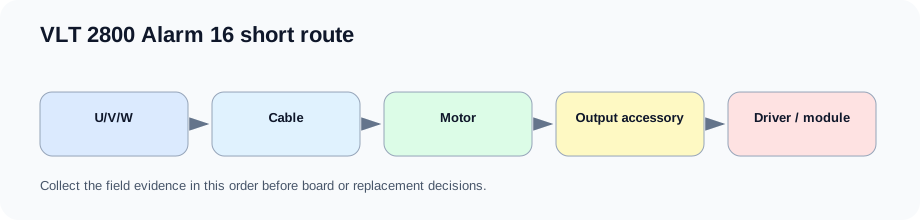
Find the short before judging the board
Alarm 16 indicates a short-circuit at the motor terminals or in the motor path. The first action is not a parameter change. The first action is boundary finding: U/V/W terminals, motor cable, winding, output contactor, output filter and terminal-box condition.
If the external path is clear, the compact drive moves onto a pre-power gate-driver route. That route compares output phase legs, driver supplies and prior repair evidence before any live test.
Alarm 16 evidence path
| Boundary | What to prove | Stop condition |
|---|---|---|
| U/V/W terminal block | No phase-to-phase short or contamination | Short found at terminals |
| Motor cable | No damage, splice fault or moving-cable short | Insulation or continuity fault |
| Motor winding | No winding short or grounded terminal-box fault | Winding fault remains |
| Output accessories | Contactor/filter/surge path not shorted | Accessory fault remains |
| Power board | Static output and driver channels compare correctly | Driver/module damage or prior repeat failure |
Field record checklist
- Fault timing
- U/V/W inspection
- Cable continuity
- Motor winding evidence
- Output contactor/filter status
- Static output check
- Driver channel comparison
- Repair history
Technical basis and reference documents
This is an independent editorial technical reference. Original manufacturer documentation remains controlling for installation, repair and commissioning decisions.
Confirms Alarm 13 overcurrent, Alarm 14 earth fault, Alarm 16 current short circuit, input-phase and DC-link alarm boundaries used to structure the first service routes.
Documents VLT 2800 warning and alarm text including Alarm 13 peak current, Alarm 14 ground fault, Alarm 15 switch-mode supply and Alarm 16 short-circuit cautions.
Provides practical Alarm 14 separation between motor/cabling evidence and drive-side current-sensor evidence, including no-motor current observations and manual-initialization caution.
Diagnostic workflow
Alarm 16 short circuit, repeat output-stage failure or post-repair uncertainty on compact Danfoss VLT 2900 hardware.
Alarm 13 overcurrent or Alarm 14 earth fault on a VLT 2800 / 2900 compact drive during start, ramp, run or bench test.
Turn this record into a qualified service request
A repair decision is much more reliable when the request includes the exact identity of the drive, the first fault evidence and the machine condition when the symptom appeared.
- Complete drive type code / MLFB or nameplate model
- Fault code, fault value and first event before reset
- When the event appears: power-up, enable, ramp, run, decel or stop
- Motor/cable connected or isolated during the symptom
- Visible board, option-card, module and connector identifiers
- Previous repair history, replacement parts and repeat-failure pattern