
Scope of this technical record
Combined Alarm 13 and Alarm 14 workflow for separating application current, motor/cable insulation and drive-side feedback evidence.
Qualified personnel only. Disconnect supply and remove motor leads safely before insulation or no-motor checks.
Alarm 13 / 14 workflow route
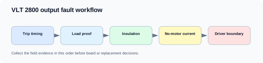
The workflow keeps motor/cable evidence ahead of current-feedback and board conclusions.
VLT 2800 output-fault workflow
Why Alarm 13 and Alarm 14 share part of the route
The two alarms are different, but both can be caused by external motor and cable conditions. The workflow starts outside the drive, then only moves inward when trip timing and no-motor evidence justify it.
This prevents a good board from being replaced while a motor cable is still compromised, and it prevents repeated reset attempts into a damaged output stage.
Isolation workflow
| Branch | Evidence | Next decision |
|---|---|---|
| Alarm 13 during ramp | Motor shaft, ramp, load, current limit | Application / parameter route first |
| Alarm 13 at first PWM | Motor cable and output terminal evidence | External short or drive-side output route |
| Alarm 14 with motor | Insulation and PE / shield evidence | Motor/cable route first |
| Alarm 14 without motor | Displayed current and reset behavior | Current feedback / board route |
| Both alarms after repair | Repair history and driver evidence | Gate-driver pre-power workflow |
Field record checklist
- Alarm number
- Trip timing
- Motor cable state
- Insulation result
- No-motor current
- Load condition
- Previous repair
Technical basis and reference documents
This is an independent editorial technical reference. Original manufacturer documentation remains controlling for installation, repair and commissioning decisions.
Confirms Alarm 13 overcurrent, Alarm 14 earth fault, Alarm 16 current short circuit, input-phase and DC-link alarm boundaries used to structure the first service routes.
Documents VLT 2800 warning and alarm text including Alarm 13 peak current, Alarm 14 ground fault, Alarm 15 switch-mode supply and Alarm 16 short-circuit cautions.
Provides practical Alarm 14 separation between motor/cabling evidence and drive-side current-sensor evidence, including no-motor current observations and manual-initialization caution.
Linked records
Alarm 13 means the inverter peak current limit has been exceeded. In service work the key is not the code text but the timing: mechanical lock, wrong motor sizing, aggressive ramp, load torque, motor cable condition, current feedback and output-stage evidence are different branches.
Alarm 14 is routed through the motor/cable insulation boundary first. If the fault appears with the motor disconnected or measured current is not near zero with no motor, the case moves inward to current sensor, feedback or compact-drive power-board evidence.
Output-stage route for Alarm 13, Alarm 14 and Alarm 16 cases after external motor, cable and terminal evidence has been collected. The route connects gate-drive channels, driver supply, current feedback and output module decisions.
Turn this record into a qualified service request
A repair decision is much more reliable when the request includes the exact identity of the drive, the first fault evidence and the machine condition when the symptom appeared.
- Complete drive type code / MLFB or nameplate model
- Fault code, fault value and first event before reset
- When the event appears: power-up, enable, ramp, run, decel or stop
- Motor/cable connected or isolated during the symptom
- Visible board, option-card, module and connector identifiers
- Previous repair history, replacement parts and repeat-failure pattern