
Scope of this technical record
Danfoss VLT Alarm 7 / DC-link overvoltage route for deceleration, quick stop, high-inertia fan, pump coast-down, conveyor stop and lowering-load cases where regenerated energy may exceed the ramp or braking path.
A drive in overvoltage or braking service can contain hazardous DC-link and brake-circuit energy after shutdown. Do not touch brake terminals or internal DC-link points until qualified isolation and discharge verification are complete.
Danfoss Alarm 7 brake-energy route
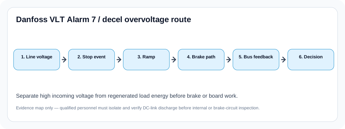
The route separates line-side overvoltage from regenerated energy before chopper or board repair.
Danfoss VLT deceleration-overvoltage route
Do not start by buying a brake resistor
A deceleration overvoltage trip is a symptom of energy management, not proof that one specific part has failed. The motor may be returning energy into the DC link because the ramp is too short for the load inertia, the application is overhauling, the line voltage is already high, or the brake path cannot absorb the energy.
The first decision is therefore simple but critical: is the voltage high before the stop event, or does it rise only when the machine decelerates? High line voltage and regenerated energy require different actions. A support request that skips this split tends to produce bad part advice.
Timing split for Alarm 7 / DC-link high
Trip timing is the fastest way to narrow the diagnostic scope. Alarm 7 at power-up points toward line or DC-link sensing evidence. Alarm 7 during deceleration points toward load energy, ramp or braking. Alarm 7 during lowering or unwinding points toward overhauling load behaviour, where the motor is acting as a generator for part of the cycle.
Deceleration overvoltage decision matrix
| Observed pattern | Most likely boundary | Evidence that makes it actionable |
|---|---|---|
| Trip only when decel ramp is short | Regenerative energy / ramp | Before/after ramp test and stop-time requirement |
| Trip on lowering or overhauling load | Machine energy entering DC link | Load direction, torque direction and brake duty evidence |
| Trip with high incoming voltage | Line-side voltage | Input phase-to-phase readings at the drive |
| Resistor installed but hot or tripping thermal | Resistor duty or placement | Ohms, wattage/duty, thermal contact and cabinet heat |
| Resistor correct but no braking action | Chopper command / brake transistor | Brake option presence and chopper evidence |
| Overvoltage appears without regenerative event | DC-link sensing / control boundary | Line, ramp and brake evidence already ruled out |
Brake path evidence before board repair
A board-level decision becomes credible only after line voltage, load inertia, ramp behaviour and the physical brake path have been documented. If a resistor is fitted, record its resistance after safe isolation, wiring route, thermal-contact state and cabinet placement. If no resistor is fitted, confirm whether the drive frame has a brake chopper or requires an external brake option.
The most common bad decision is replacing power electronics after every overvoltage trip. The better route is to prove whether the brake system was ever able to absorb the regenerated energy. Only then should the case move toward brake transistor, DC-link feedback or control-board investigation.
- Record the exact stop event that creates Alarm 7
- Capture input phase-to-phase voltage at the drive
- Change ramp only as a controlled diagnostic when the process allows it
- Verify brake resistor value and thermal circuit after isolation
- Confirm brake-chopper option and command evidence before board repair
Field record checklist
- Full type code and voltage class
- Alarm/warning text and trip timing
- Input voltage readings
- Deceleration ramp setting and stop requirement
- Load inertia or overhauling-load description
- Brake resistor value, label, wiring and thermal-contact status
- Previous resistor, chopper or drive-board replacement history
Technical basis and reference documents
This is an independent editorial technical reference. Original manufacturer documentation remains controlling for installation, repair and commissioning decisions.
Defines Alarm 7 / DC-link overvoltage checks around input phase-to-phase voltage and regenerative voltage from the motor end.
Describes brake-resistor function as absorbing brake power generated in regenerative braking and supports the brake-energy route used here.
Explains why external brake-resistor placement can improve heat handling, duty-cycle selection and braking-energy dissipation.
Diagnostic workflow
Turn this record into a qualified service request
A repair decision is much more reliable when the request includes the exact identity of the drive, the first fault evidence and the machine condition when the symptom appeared.
- Complete drive type code / MLFB or nameplate model
- Fault code, fault value and first event before reset
- When the event appears: power-up, enable, ramp, run, decel or stop
- Motor/cable connected or isolated during the symptom
- Visible board, option-card, module and connector identifiers
- Previous repair history, replacement parts and repeat-failure pattern