
Scope of this technical record
Danfoss VLT Alarm 4 mains phase-loss route for deciding whether the drive is seeing a missing phase, unbalanced phase voltage, upstream fuse/contactor failure, loose input terminal, plant line sag, rectifier evidence or internal DC-link sensing problem.
Input-terminal checks involve hazardous live voltage and must be performed only by qualified personnel with appropriate procedure and PPE. A missing phase can still leave dangerous voltage inside the drive. Verify isolation and DC-link discharge before internal inspection.
Danfoss Alarm 4 supply route
Alarm 4 is routed through measured supply evidence at the drive terminals before internal repair.
Danfoss Alarm 4 mains phase-loss image
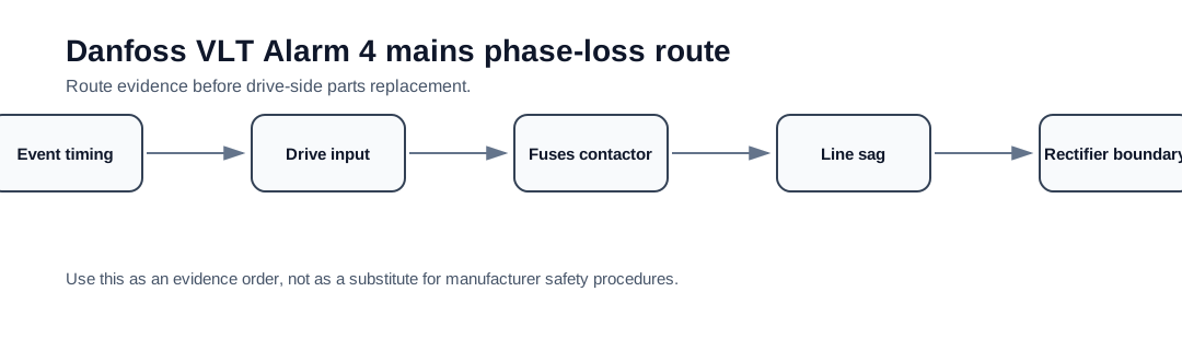
Alarm 4 starts at the drive input terminals
Danfoss service guidance describes Alarm 4 as mains phase loss and directs the technician to measure input voltage phase-to-phase and confirm the phases are balanced. The important detail is location: the measurement must be made at the drive input terminals under the condition that produces the alarm, not only at the upstream distribution panel.
A contactor pole, fuse holder, disconnect, line reactor terminal or loose lug can drop a phase only when current flows. The drive may show Alarm 4 even when an upstream meter reading looked acceptable minutes earlier. That is why this page routes Alarm 4 through a field supply proof before rectifier or DC-link sensing is considered.
Alarm 4 timing and supply evidence
The first timing split is power-up, ready state, run command or plant-load change. Alarm 4 at power-up often points to a missing phase, wiring error or failed protection device. Alarm 4 that appears when another load starts may indicate line sag or contactor heating. Alarm 4 after maintenance may indicate swapped phases, loose terminals or a fuse not seated correctly.
Alarm 4 decision matrix
| Observed pattern | First boundary | Evidence that moves the case forward |
|---|---|---|
| Alarm appears at power-up | Supply path / missing phase | L1-L2, L2-L3, L1-L3 values at drive terminals |
| Alarm appears only when drive starts | Fuse, contactor or line impedance under load | Loaded phase readings and thermal evidence at protection devices |
| Alarm appears when other plant load starts | Plant supply sag or imbalance | Timestamped voltage comparison before/after load event |
| All phases stable at drive input | Rectifier, DC-link ripple or sensing boundary | Safe internal evidence package after isolation |
| Recent wiring or panel work | Input terminal / phase routing error | Photos of terminal order, torque evidence and line protection path |
When Alarm 4 becomes a drive-side case
Alarm 4 becomes a drive-side repair case only after the supply route is credible. If all three phase-to-phase values are balanced at the drive input during the event, the service route moves inward to rectifier input, DC-link ripple, voltage-sensing path and control electronics. Even then, the support request should include the field measurements that prove the supply was not the cause.
- Record phase-to-phase voltage at the drive terminals
- Compare no-load and loaded readings if the alarm appears during run
- Inspect fuses, disconnect, contactor poles, line reactor and terminal torque
- Photograph input wiring and protection path before changes
- Escalate inward only after the input route is proven stable
Field record checklist
- Full VLT type code and voltage class
- Alarm 4 event timing
- L1-L2 / L2-L3 / L1-L3 readings at drive input terminals
- Input fuse, contactor and disconnect evidence
- No-load versus load voltage comparison
- Photos of input wiring and recent maintenance work
Technical basis and reference documents
This is an independent editorial technical reference. Original manufacturer documentation remains controlling for installation, repair and commissioning decisions.
Used to anchor Alarm 4 as a mains phase-loss check, Alarm 29 as a drive over-temperature check and DC-link overvoltage as a supply/regeneration/brake-path issue.
Used to keep Alarm 29 diagnosis focused on real heatsink temperature, airflow, fan condition, ambient temperature and load before sensor or board conclusions.
Used as public VLT-family context for heatsink temperature alarm wording, high-voltage safety and FC-family drive service boundaries.
Diagnostic workflow
Turn this record into a qualified service request
A repair decision is much more reliable when the request includes the exact identity of the drive, the first fault evidence and the machine condition when the symptom appeared.
- Complete drive type code / MLFB or nameplate model
- Fault code, fault value and first event before reset
- When the event appears: power-up, enable, ramp, run, decel or stop
- Motor/cable connected or isolated during the symptom
- Visible board, option-card, module and connector identifiers
- Previous repair history, replacement parts and repeat-failure pattern