
Scope of this technical record
Evidence package for 6SE70 terminal/expansion wiring involved in motor thermal sensing and brake-control symptoms.
Terminal and expansion-interface work must be performed with power isolated and the machine secured. Thermal and brake protection must remain functional after repair.
6SE70 terminal expansion evidence route
The interface record links drive terminals to external thermal and brake hardware evidence.
6SE70 terminal expansion evidence map
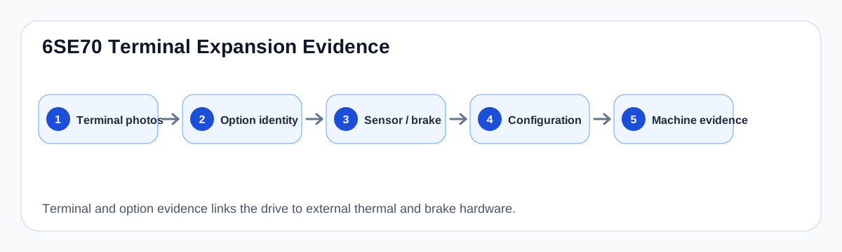
What the interface record should show
This record exists because thermal and brake symptoms often involve external machine wiring, not only the drive controller. Photos should show terminal labels, wire destinations, option/expansion board identity, brake coil wiring, sensor wiring and cabinet environment.
The record should also document the configured response: whether the input is intended as a warning, trip, brake acknowledgement or timed brake command. Without that, a board label alone is not enough to route repair.
Interface evidence map
| Symptom | Interface evidence | External evidence |
|---|---|---|
| KTY/PTC warning | Sensor terminals and configuration | Motor sensor, cooling and cable |
| Brake release failure | Output/relay terminal and timing | Coil voltage and mechanical brake |
| Intermittent trip | Loose/contaminated terminal route | Vibration, heat and cabinet environment |
| After retrofit | Option board identity | Changed wiring or parameter baseline |
Field record checklist
- Terminal photos
- Option/expansion board identity
- Thermal sensor type
- Brake wiring
- Configured response
- External machine evidence
Technical basis and reference documents
This is an independent editorial technical reference. Original manufacturer documentation remains controlling for installation, repair and commissioning decisions.
OEM basis for 6SE70 / 6SE71 safety, control connections, motor temperature evaluation and option context.
Internal technician note set used only to structure public diagnostic routes around KTY/PTC thermal protection and brake-control evidence.
Linked circuit records
Routes KTY84 and PTC motor-temperature evidence through terminal input, expansion-board context and configured warning/fault response.
Maps drive brake-control logic to relay output, brake coil supply, release/close delays and mechanical brake condition for hoist and vertical-axis applications.
Turn this record into a qualified service request
A repair decision is much more reliable when the request includes the exact identity of the drive, the first fault evidence and the machine condition when the symptom appeared.
- Complete drive type code / MLFB or nameplate model
- Fault code, fault value and first event before reset
- When the event appears: power-up, enable, ramp, run, decel or stop
- Motor/cable connected or isolated during the symptom
- Visible board, option-card, module and connector identifiers
- Previous repair history, replacement parts and repeat-failure pattern