
Scope of this technical record
Evidence checklist for Danfoss VLT Alarm 14 and Alarm 16 repair requests, defining what must be captured before a power-output, current-sensing, gate-driver or module repair decision is made.
This record is not a live-test instruction. Collect evidence under the plant's qualified isolation procedure. Do not power a drive with a suspected output short or earth fault just to reproduce the alarm for photos.
Danfoss output repair evidence route
The record defines the evidence needed before current-sensor, gate-driver or module repair decisions.
Danfoss output repair evidence image
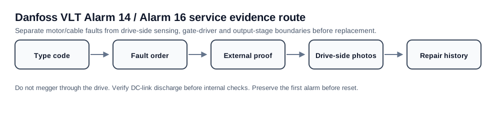
Output repair intake matrix
This record prevents a short alarm label from becoming an unsupported module quote.
| Evidence item | Decision enabled | Missing-data risk |
|---|---|---|
| Type code / frame | Correct hardware family | Wrong board or module |
| Connected vs disconnected output | External versus internal boundary | Repeat field fault |
| Repair history | Repeat-failure risk | Another failed module |
Why an evidence record is needed
A Danfoss VLT output-fault repair request often arrives as a short message: Alarm 14 or Alarm 16. That is not enough to decide whether to quote a module, current sensor, power board, field wiring correction or replacement drive. The evidence record turns the alarm into a service case that can be checked before parts are ordered.
The goal is to protect the repair path. A repaired power stage will not survive if the motor cable still leaks to earth or an output contactor still creates a phase short. A field installation will not be fixed by replacing the drive when the real issue is a wet motor box. Evidence controls that decision.
Minimum intake package
The record should capture identity, fault timing, external output proof and drive-side evidence where escalation is justified. Missing identity or missing connected/disconnected results usually means the support response should stay at diagnostic guidance rather than a board quote.
Alarm 14/16 intake evidence
| Evidence item | Purpose | Acceptable example |
|---|---|---|
| Nameplate / type code | Confirms frame and hardware family | Clear photo of VLT type code and rating |
| Fault queue and timing | Separates first alarm from secondary alarms | Photo before reset plus event description |
| Motor/cable result | Defines external versus drive-side path | Insulation record and drive-terminal disconnection result |
| Output terminal photos | Finds contamination, loose strands or accessory wiring | U/V/W, PE and output accessories visible |
| Drive-side photos | Supports module, driver or current-sensor repair | Power module/current sensor/power board labels and damage |
| Repair history | Prevents repeat failure | What was replaced and what failed again |
Decision outputs from the record
The evidence record should end with one of four outcomes: field motor/cable repair, output accessory correction, drive-side repair assessment, or replacement/retrofit planning. If the outcome is still just the alarm number, the intake is incomplete.
- Field repair: alarm follows motor, cable, terminal box or output accessory
- Drive repair: alarm remains with external path proven clear and drive-side evidence exists
- Repeat-failure review: prior module or board was replaced without proving cause
- Replacement planning: frame is obsolete, parts are scarce, or downtime risk exceeds repair value
Field record checklist
- VLT nameplate photo
- Fault display before reset
- Trip timing and application state
- Motor/cable insulation record
- Output terminal photo set
- Drive-side module/sensor/board evidence
Technical basis and reference documents
This is an independent editorial technical reference. Original manufacturer documentation remains controlling for installation, repair and commissioning decisions.
Used to anchor Alarm 14 around motor/cabling isolation and the boundary where current-sensor or drive-side investigation becomes relevant.
Used to anchor Alarm 14 as short-to-ground in motor/wiring and Alarm 16 as line-to-line short circuit in motor/wiring.
Used as FC-family public manual context for alarm wording, DC-link safety and output-side service boundaries.
Linked circuit records
Turn this record into a qualified service request
A repair decision is much more reliable when the request includes the exact identity of the drive, the first fault evidence and the machine condition when the symptom appeared.
- Complete drive type code / MLFB or nameplate model
- Fault code, fault value and first event before reset
- When the event appears: power-up, enable, ramp, run, decel or stop
- Motor/cable connected or isolated during the symptom
- Visible board, option-card, module and connector identifiers
- Previous repair history, replacement parts and repeat-failure pattern