
Scope of this technical record
OVER I TRIP route for separating real armature overcurrent from autotune/calibration errors, unstable current-loop tuning, current-feedback hardware trouble and control-board A/D evidence.
Do not repeatedly reset an OVER I TRIP under load. Isolate before internal inspection. Any live comparison between displayed current and measured current requires qualified procedures and appropriate equipment.
590P OVER I TRIP current route
The route separates real armature current from false current feedback before bridge or control-board decisions.
590P OVER I TRIP current-feedback route
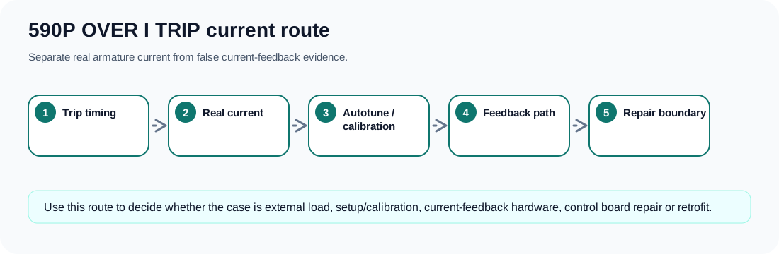
What the alarm means — and what it does not prove
OVER I TRIP means the drive has decided armature current exceeded the permitted trip boundary. That does not automatically prove the motor actually drew destructive current. On a legacy DC converter, the same visible fault can come from a jammed load, a motor armature problem, wrong calibration, missing or poor autotune, unstable manual current-loop tuning, corrupted current feedback or a control-board feedback input fault.
The first repair question is therefore not “which board is bad?” It is “is the drive reporting real current, or is the current-feedback chain lying?” Until that split is made, a service answer is no better than a generic alarm table.
Trip timing changes the diagnosis
Classify the first event before changing current limits or removing boards.
OVER I TRIP timing map
| When the trip appears | First boundary to prove | Reason |
|---|---|---|
| During autotune | Motor data, field, current calibration and feedback hardware | The loop is being identified; bad data or bad feedback can look like overcurrent |
| At first armature current demand | ACCT / feedback plug, bridge condition and field presence | Instant trips often separate false feedback from a hard power path fault |
| Only during acceleration or heavy load | Machine load, brake release, armature wiring and current limit | This is the most likely real-current path |
| During reversing or regeneration | Regenerative bridge group, speed feedback and field weakening | The symptom can be quadrant-specific |
| After board or parameter replacement | Calibration, copied parameters, connector seating and board revision | A setup mismatch can create a new current-loop fault |
| With impossible current display | Current-feedback scaling, burden, A/D input or low-voltage rails | The motor current may not match what the controller believes |
Real current versus false feedback
A real-current case usually has matching machine evidence: load change, brake not released, shorted armature, poor commutator/brush condition, insulation trouble, mechanical jam, wrong field or acceleration demand. A false-feedback case often has an implausible current value, trip with little or no torque, trouble after connector movement or repair, failed autotune with a current-feedback hint, or unstable current display.
The armature bridge should not be the first suspect in every case. If current is real, the bridge may be a victim. If current is false, the bridge may be good and the feedback path is the fault. If the current loop is unstable, neither a bridge nor a board swap fixes the root cause until tuning and calibration are corrected.
- Prove field before judging armature behaviour.
- Compare drive-reported current with external evidence when qualified measurement is possible.
- Treat ACCT / feedback plug disturbance as important history.
- Treat manual tuning and copied parameters as possible fault sources.
- Escalate to control-board repair only after external and calibration evidence is coherent.
Repair decision boundary
A useful support request should include the exact type code, current rating, regenerative status, armature and field ratings, first-fault timing, whether autotune passed, whether parameters were copied from another machine, displayed current at the event, external current evidence, field state, speed-feedback type and board/connector photos.
That package lets the repair route split into motor/load correction, parameter and autotune correction, current-feedback board repair, firing/bridge inspection, donor-drive matching or a planned retrofit. Without it, the answer can only be a fault-code definition.
Field record checklist
- Type code and current rating
- Regenerative status
- First-fault timing
- Autotune result
- Calibration and parameter history
- Displayed versus measured current
- ACCT / feedback plug photos
- Field and speed-feedback evidence
Technical basis and reference documents
This is an independent editorial technical reference. Original manufacturer documentation remains controlling for installation, repair and commissioning decisions.
Official source for OVER I TRIP: armature current above calibration value; possible causes include missing autotune, incorrect calibration and unstable current loop.
Official source for 590+ safety boundaries, permanent earthing, field/armature context and parameterised DC-drive operation.
Official converter reference describing current-feedback related trip protection and the importance of feedback hardware in external-stack cases.
Internal reviewed drawings used only as functional evidence for supply, feedback, burden, firing and bridge path mapping; original drawings are not redistributed.
Diagnostic workflow
Turn this record into a qualified service request
A repair decision is much more reliable when the request includes the exact identity of the drive, the first fault evidence and the machine condition when the symptom appeared.
- Complete drive type code / MLFB or nameplate model
- Fault code, fault value and first event before reset
- When the event appears: power-up, enable, ramp, run, decel or stop
- Motor/cable connected or isolated during the symptom
- Visible board, option-card, module and connector identifiers
- Previous repair history, replacement parts and repeat-failure pattern