
Scope of this technical record
Maps the PowerFlex DPI/HIM communication route from control board port to cable, HIM/adapter, network device and cabinet EMC evidence.
Confirm machine safe state before disconnecting operator-interface, adapter or network hardware that may carry command or reference information.
PowerFlex DPI / HIM route
Port-loss faults need device and installation evidence before internal port conclusions.
PowerFlex DPI/HIM communication path image
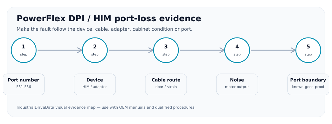
DPI/HIM is a physical route
A port-loss trip often looks like software, but the evidence route is physical: drive port, cable bend, door-mounted HIM, adapter seating, network state, grounding and motor-lead separation.
Communication-route evidence
The path should be tested by substitution and movement sensitivity where site procedure allows.
DPI/HIM path
| Node | Evidence | Conclusion |
|---|---|---|
| Drive port | Same port fails with known-good device | Possible port/control-board boundary |
| DPI cable | Fault follows cable or door movement | Cable/routing issue |
| HIM/keypad | Fault follows HIM | Operator-interface issue |
| Adapter/network | Adapter status or controller event aligns | Network/device route |
| Cabinet noise | Fault appears with contactor/motor switching | EMC/grounding route |
Field record checklist
- Port number
- Device identity
- Cable movement
- Adapter status
- EMC context
Technical basis and reference documents
This is an independent editorial technical reference. Original manufacturer documentation remains controlling for installation, repair and commissioning decisions.
OEM context for drive interfaces and control wiring practices.
Turn this record into a qualified service request
A repair decision is much more reliable when the request includes the exact identity of the drive, the first fault evidence and the machine condition when the symptom appeared.
- Complete drive type code / MLFB or nameplate model
- Fault code, fault value and first event before reset
- When the event appears: power-up, enable, ramp, run, decel or stop
- Motor/cable connected or isolated during the symptom
- Visible board, option-card, module and connector identifiers
- Previous repair history, replacement parts and repeat-failure pattern