
Scope of this technical record
Danfoss VLT input-phase and DC-link path for routing Alarm 4 mains phase loss and DC-link overvoltage/undervoltage evidence through input terminals, fuses, contactor, rectifier, precharge, DC-link capacitors, brake chopper and bus-sense feedback.
The input and DC-link path contains lethal voltages. Qualified personnel must isolate, lock out and verify DC-link discharge before any internal inspection. Do not use the DC bus as a casual measurement point.
Danfoss input / DC-link route
The same energy path explains phase-loss and overvoltage symptoms from different directions.
Danfoss input and DC-link path image
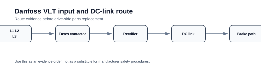
One path explains several different alarms
Alarm 4, DC-link undervoltage and deceleration overvoltage are different symptoms on the same energy path. The path begins at L1/L2/L3, passes through fuses, disconnect or contactor hardware, rectifier and precharge, then appears as DC-link energy that may also be affected by braking and regenerated load energy.
The service value of this page is boundary control. Supply evidence stays outside the drive until it is proven. DC-link and brake evidence stay hazardous until qualified isolation is complete. The page prevents a missing phase, weak contactor or regenerative stop event from being treated as the same repair request.
Input/DC-link evidence map
The technician should document the route in order. For Alarm 4, the strongest evidence is balanced voltage at the drive input under the fault condition. For overvoltage during deceleration, the strongest evidence is timing with ramp, load inertia and braking path. For undervoltage or sag, the strongest evidence is supply collapse, precharge behaviour and DC-link charge history.
Energy-path evidence
| Path area | What it proves | Relevant alarm family |
|---|---|---|
| L1/L2/L3 input terminals | Whether the drive actually receives balanced supply | Alarm 4 / undervoltage |
| Fuses / disconnect / contactor | Whether a single pole opens under load | Alarm 4 / intermittent ready loss |
| Rectifier / precharge | Whether energy reaches the DC link correctly | Undervoltage / no-ready / precharge faults |
| DC-link capacitors / bus sense | Whether stored energy and measurement are credible | Overvoltage / undervoltage |
| Brake chopper / resistor | Whether regenerated energy has a route | Deceleration overvoltage |
Repair boundary
The input/DC-link path becomes a board or module case only when external supply, protection devices and load/brake conditions have been documented. A repair request should include photos of the input path, braking hardware where fitted, the drive type code and the event timing. If a drive has been idle for a long period, capacitor condition and controlled recommissioning history may also be relevant.
Field record checklist
- Input terminal readings
- Protection path photos
- DC-link event timing
- Ramp/load/brake condition
- Precharge or idle-storage history
- Exact type code and frame
Technical basis and reference documents
This is an independent editorial technical reference. Original manufacturer documentation remains controlling for installation, repair and commissioning decisions.
Used to anchor Alarm 4 as a mains phase-loss check, Alarm 29 as a drive over-temperature check and DC-link overvoltage as a supply/regeneration/brake-path issue.
Used to keep Alarm 29 diagnosis focused on real heatsink temperature, airflow, fan condition, ambient temperature and load before sensor or board conclusions.
Used as public VLT-family context for heatsink temperature alarm wording, high-voltage safety and FC-family drive service boundaries.
Turn this record into a qualified service request
A repair decision is much more reliable when the request includes the exact identity of the drive, the first fault evidence and the machine condition when the symptom appeared.
- Complete drive type code / MLFB or nameplate model
- Fault code, fault value and first event before reset
- When the event appears: power-up, enable, ramp, run, decel or stop
- Motor/cable connected or isolated during the symptom
- Visible board, option-card, module and connector identifiers
- Previous repair history, replacement parts and repeat-failure pattern