
AC drives and DC drives
Technical records for legacy ABB industrial drives, beginning with the ACS800 AC drive and DCS800 DC drive families: board functions, fault routing, interface paths and controlled diagnostic workflows.
Scope of this technical record
ABB brand-level hub for ACS510/ACS550 standard drives, ACS800 AC drives and DCS800 DC drives, now organised by service evidence rather than by a generic brand description.
This record is for qualified industrial-drive personnel. Isolate the drive, verify stored DC energy is discharged and follow the manufacturer manual before measuring inside the converter or touching motor, brake, field or control wiring.
ABB drive fault evidence route
ABB cases are routed from the first event to a proven external or interface boundary before hardware replacement.
ABB fault evidence map
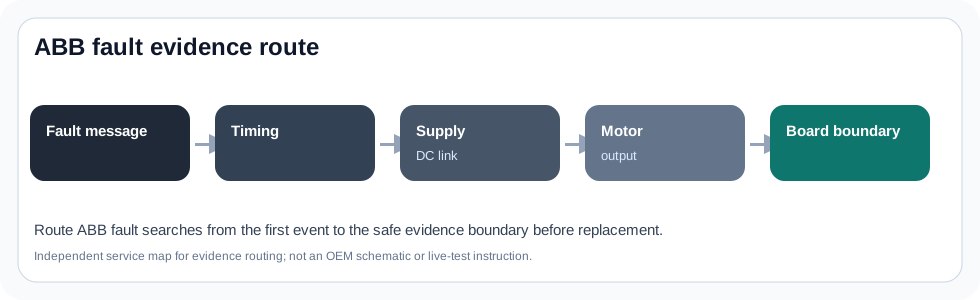
ABB pages now split by drive family
ABB demand is not one market. ACS510/ACS550 users usually need standard-drive fault triage: undervoltage, overcurrent, keypad evidence, terminals and maintenance wear. ACS800 users need a deeper interface and power-stage map around PPCC LINK, SHORT CIRC, RMIO, INT/AINT and AGDR-linked power hardware. DCS800 users need DC-drive evidence around armature, field, field exciter and SDCS control/power boards.
This page therefore sends each technician into the right evidence path instead of offering a single ABB troubleshooting paragraph. The goal is to make the first support request specific enough to avoid a wrong board, wrong module or unnecessary complete-drive replacement.
ABB service entry map
| Technician problem | Primary family route | First evidence boundary |
|---|---|---|
| DC UNDERVOLT 3220 / LINE CONV FF51 | ACS510 / ACS550 standard-drive records | Input, fuses, precharge, DC link and line-converter context |
| OVERCURRENT 2310 | ACS510 / ACS550 plus generic output-stage workflow | Trip timing, motor/cable, load and current feedback |
| PPCC LINK 5210 | ACS800 interface records | Control-board supply, PPCC link, INT/AINT/PBU branch |
| SHORT CIRC 2340 | ACS800 output-stage records | Motor cable, IGBT module and AGDR/gate-driver boundary |
| F521 FieldAck | DCS800 field-exciter records | Field circuit, FEX/DCF exciter, Mot1FexStatus and SDCS configuration |
What makes these pages different
Most public results either quote the manual or sell a repair. These pages connect official fault wording to the practical route a technician needs: first event, power or output boundary, internal interface, board identity and stop conditions.
The result is not a schematic leak and not a service guarantee. It is a public evidence layer that tells the technician what must be known before a repair, replacement, retrofit or quote can be responsible.
Field record checklist
- ABB family and exact type code
- Fault text/code and first event sequence
- Photos of terminals, keypad and board identifiers where safe
- External supply/motor/field evidence
- Prior board or module replacement history
Technical basis and reference documents
This is an independent editorial technical reference. Original manufacturer documentation remains controlling for installation, repair and commissioning decisions.
Used for ABB fault-word, automatic reset and line-converter context that informs how ABB fault pages should preserve timing and line-side evidence.
Editorial evidence model for type code, fault log, trip timing, terminal wiring, motor/cable condition and maintenance observations.
Official source for PPCC LINK, SHORT CIRC, FAULTED INT INFO, INT SC INFO, automatic reset and line-converter references.
Field discussions confirm why PPCC LINK cases often need connector, fibre, power-supply and board-branch evidence rather than immediate module replacement.
Official source for DCS800 safety instructions, D1-D7 scope, FieldAck F521 logic and field-exciter status routing.
Editorial record format for SDCS-CON-4, SDCS-POW-4, SDCS-PIN-51, FEX/DCF field exciter and armature/field measurement evidence.
Available series
DCS800 service hub for F521 FieldAck, field-exciter acknowledgement, DCSLink field communication, SDCS-CON-4 control electronics, SDCS-POW-4 auxiliary supply and SDCS-PIN-51 measurement/interface evidence on D5-D7 converter modules.
ACS800 service hub for PPCC interface faults and destructive output-stage events, including SHORT CIRC 2340, motor-cable isolation, phase-leg evidence, AGDR gate-driver boundaries and IGBT module repair or modernization decisions.
ACS800 service hub for PPCC LINK, RMIO/RDCU control power, INT/AINT inverter-interface routing, PBU branch evidence and power-stage boundaries before a board, donor-unit or modernization decision.
ACS800 service hub for technicians who need to choose the first safe path from a visible fault or machine symptom: PPCC link, RMIO/RDCU control supply, INT/AINT interface, AGDR gate driver, output bridge, or modernization boundary.
DCS800 service hub for DC motor cases where field acknowledgement, electronics supply, SDCS-CON-4 control, SDCS-POW-4 supply, SDCS-PIN-51 measurement and field-exciter evidence must be separated before repair or upgrade decisions.
ACS510 and ACS550 coverage captures the high-frequency field-service layer: keypad operation, terminal control, DC undervoltage, overcurrent at acceleration, line-converter indication and maintenance evidence before a board or drive exchange is considered.
ACS800 coverage starts where repair decisions become expensive: PPCC communication between control and inverter interface electronics, short-circuit trips around the power stage, and AGDR-linked IGBT driver/module identification for larger frames.
DCS800 coverage organizes the D1–D7 converter platform around the control, power-supply, measurement and field-exciter relationships that technicians need when an older DC drive cannot be returned to service safely.
Turn this record into a qualified service request
A repair decision is much more reliable when the request includes the exact identity of the drive, the first fault evidence and the machine condition when the symptom appeared.
- Complete drive type code / MLFB or nameplate model
- Fault code, fault value and first event before reset
- When the event appears: power-up, enable, ramp, run, decel or stop
- Motor/cable connected or isolated during the symptom
- Visible board, option-card, module and connector identifiers
- Previous repair history, replacement parts and repeat-failure pattern