
Scope of this technical record
Workflow for converting a 590P MISSING PULSE report into line-reference, connector, firing-output, gate path, bridge and retrofit evidence.
Do not perform live bridge or gate measurements without qualified procedures and appropriate equipment. Preserve evidence instead of repeated resets under load.
590P missing-pulse workflow route
The workflow turns a missing-pulse text into line, connector, gate and bridge evidence.
590P MISSING PULSE workflow
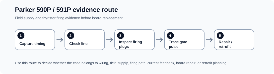
Workflow sequence
The sequence keeps a firing-path fault from becoming an automatic SCR bridge replacement.
590P MISSING PULSE workflow
| Step | Evidence | Decision |
|---|---|---|
| 1 | 590P / 591P configuration and regenerative status | Know which bridge group can be involved |
| 2 | Trip timing: enable, motoring load, regeneration or recent repair | Separate line/contact/firing/bridge conditions |
| 3 | Input phases, fuses, contactor and line reference | Clear external line-reference causes |
| 4 | Firing plug, harness and gate wiring photos | Find connector and wiring faults before bridge decisions |
| 5 | Firing output or waveform evidence | Separate missing command from non-conducting SCR |
| 6 | Board and bridge labels | Choose repair, donor board, bridge repair or retrofit |
Evidence that improves a support answer
A support request that includes only “MISSING PULSE” forces a generic answer. The request becomes useful when it includes load condition, regenerative status, recent work, firing connector photographs and whether any current waveform or fault capture exists.
- Line condition at the drive
- Regenerative/non-regenerative status
- Firing connector and harness photos
- Bridge and control-board labels
- Current waveform or trip capture
- Recent repair history
Field record checklist
- Hardware status
- Trip timing
- Line/reference proof
- Firing connector proof
- Bridge labels
- Retrofit constraints
Technical basis and reference documents
This is an independent editorial technical reference. Original manufacturer documentation remains controlling for installation, repair and commissioning decisions.
Primary product manual context for 590+ digital DC drive fault handling, safety boundaries and field/firing evidence routes.
Shows FIELD FAILED routing through field volts, external jumper positions, FL1/FL2 connection and wiring tightness before the drive is treated as failed.
A field technician case showing the real case behaviour behind mature SSD 590 Missing Pulse faults and current-waveform evidence requests.
Public support note connecting FIELD FAIL to field motor wiring, field fuses, field resistance checks and hardware repair boundary.
Linked records
MISSING PULSE is not simply a failed thyristor bridge. The evidence route must separate line phase/reference, firing connector integrity, pulse-transformer or gate wiring, SCR bridge condition and current-waveform feedback before replacement hardware is selected.
Routes MISSING PULSE through AC line reference, firing command generation, firing plugs, pulse transformer or isolation path, SCR gate wiring, bridge conduction and armature-current waveform evidence.
Turn this record into a qualified service request
A repair decision is much more reliable when the request includes the exact identity of the drive, the first fault evidence and the machine condition when the symptom appeared.
- Complete drive type code / MLFB or nameplate model
- Fault code, fault value and first event before reset
- When the event appears: power-up, enable, ramp, run, decel or stop
- Motor/cable connected or isolated during the symptom
- Visible board, option-card, module and connector identifiers
- Previous repair history, replacement parts and repeat-failure pattern