
Scope of this technical record
ACS510 / ACS550 page depth for overcurrent workflow, with field-to-bench evidence routing and repair-request qualification.
This record is for qualified industrial-drive personnel. Isolate the drive, verify stored DC energy is discharged and follow the manufacturer manual before measuring inside the converter or touching motor, brake, field or control wiring.
ABB overcurrent workflow route
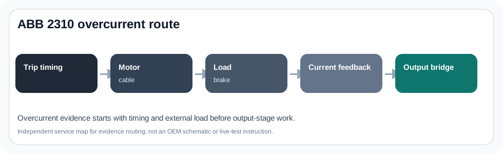
The workflow keeps 2310 on timing and field evidence before IGBT work.
ABB acs510 acs550 overcurrent workflow evidence image
What this page is meant to decide
This page deepens the ABB ACS510 / ACS550 standard-drive route for overcurrent workflow. The useful service answer is not a one-line definition; it is whether the event starts on the input energy path, output motor path, terminal command path, ageing-maintenance path or internal electronics boundary.
The page is written for field evidence capture first. That means a technician should be able to collect the type code, fault text, trip timing, wiring photos and maintenance observations before the case is escalated to board repair or whole-drive replacement.
ABB standard-drive service split
ACS510 and ACS550 cases often arrive with a panel message but without the conditions that make the message meaningful. A power-up undervoltage, a run-command overcurrent and a reset request after a cleared fault all require different evidence.
The route therefore separates four layers: line-side supply and DC link, motor/output path, control-terminal command source, and wear or environment evidence. Treating all ABB standard-drive faults as board failure creates false positives and can make a replacement drive fail for the same external reason.
Evidence split for ACS510 / ACS550 pages
| Evidence area | Why it matters | What to capture |
|---|---|---|
| Type code and voltage/current class | Confirms the installed platform and voltage family | Full nameplate, option codes, input/output rating |
| Fault timing | Separates power-up, run, ramp, decel and reset cases | When the message appears and what the machine was doing |
| Input/DC-link path | Undervoltage and line-converter cases start here | Input phases, fuses, contactor, bus-rise evidence |
| Output/motor path | Overcurrent and ground/output faults may be external | Motor cable, terminal box, load and output accessories |
| Control-terminal path | Start/reference/reset issues can mimic drive failure | DI/AI wiring, local/remote status, relay outputs |
Service route
This workflow splits an overcurrent by trip timing and external boundary before moving to inverter hardware, current feedback or gate-driver checks.
The page intentionally avoids unsupported component prescriptions. It defines the evidence that decides whether the next step is parameter correction, wiring repair, motor/cable work, maintenance replacement, board-level diagnosis or full drive replacement.
Field record checklist
- Complete ACS510/ACS550 type code and voltage class
- Fault text/code plus first-fault timing
- Local/remote status and command source
- Input, motor and terminal photos
- Maintenance history: fan, dust, capacitor age, prior repair
Technical basis and reference documents
This is an independent editorial technical reference. Original manufacturer documentation remains controlling for installation, repair and commissioning decisions.
Used for ABB fault-word, automatic reset and line-converter context that informs how ABB fault pages should preserve timing and line-side evidence.
Editorial evidence model for type code, fault log, trip timing, terminal wiring, motor/cable condition and maintenance observations.
Linked records
The output current is excessive or being measured as excessive. The diagnosis must separate motor/load/cable causes from acceleration settings, encoder/feedback issues and inverter power-stage damage.
Organizes reference voltage, analog input, digital input, relay output and auxiliary 24 V terminal evidence for start/stop, direction, speed-reference and external-fault issues.
Turn this record into a qualified service request
A repair decision is much more reliable when the request includes the exact identity of the drive, the first fault evidence and the machine condition when the symptom appeared.
- Complete drive type code / MLFB or nameplate model
- Fault code, fault value and first event before reset
- When the event appears: power-up, enable, ramp, run, decel or stop
- Motor/cable connected or isolated during the symptom
- Visible board, option-card, module and connector identifiers
- Previous repair history, replacement parts and repeat-failure pattern