
Scope of this technical record
Functional path for ATV61 / ATV71 OSF and USF evidence, covering incoming line, fuses, contactor, rectifier, precharge, DC-link capacitors, PA/PC bus measurement, brake chopper and braking resistor route.
This is a functional evidence map, not an instruction to probe a live DC link without qualification. Use the product manual and site safety procedure; verify discharge before internal DC-link, precharge or braking inspection.
Input / DC-link voltage path
The path explains why OSF and USF are opposite symptoms on the same energy route.
ATV61 / ATV71 input DC-link path image
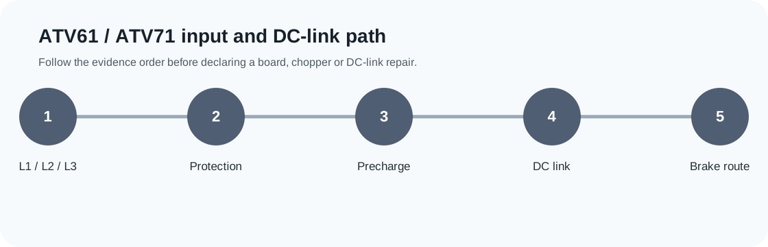
Input/DC-link path decision matrix
This path determines whether the voltage fault belongs to field supply, charging, storage, braking or internal feedback.
| Path area | Decision | Evidence |
|---|---|---|
| Input terminals | Field supply or protection | Measured L1/L2/L3 at the drive |
| Precharge / DC link | Charging and storage path | Bus rise, PA/PC measurement and capacitor evidence |
| Brake path | Regeneration handling | Resistor, chopper, wiring and thermal proof |
The same energy route creates opposite symptoms
USF and OSF are not unrelated faults. They are opposite failures on the same energy route. A low or collapsing DC link creates USF. A high or rising DC link creates OSF. The useful diagnostic map therefore follows the energy path from the line terminals through charging and storage to braking and bus feedback.
ATV61 / ATV71 energy-path checkpoints
| Path area | Fault evidence | Service implication |
|---|---|---|
| Input terminals | Line low, high, missing or unstable | Field supply problem before internal repair |
| Fuses / contactor | Voltage present upstream but not at drive | Protection or switching path issue |
| Rectifier / precharge | Bus fails to rise or rises slowly | Charging path or rectifier boundary |
| DC-link capacitors / PA-PC | Bus low, unstable or high | Storage or measurement route |
| Brake chopper / resistor | OSF during stop | Regeneration and braking route |
Input-side evidence for USF
USF evidence starts at the drive terminals. A fuse holder, contactor pole, loose terminal or undersized supply path can create a low bus while upstream voltage appears acceptable. The input path should be measured under the same condition that causes the fault, not only with the machine idle.
- Line-to-line voltage at L1/L2/L3 under the fault condition
- Fuse, disconnect and contactor photo evidence
- Heat marks or loose terminal evidence
- Precharge sequence and bus-rise evidence where qualified
- DC-link measurement at PA(+)/PC(-) where qualified
Brake and regeneration evidence for OSF
OSF during deceleration is routed through machine energy first. If the load can return energy faster than the drive can dissipate it, the bus will rise even when the control board is healthy. The brake resistor and chopper route must therefore be documented before internal repair conclusions.
- Regenerative load type and stopping profile
- Deceleration ramp and any controlled change made for diagnosis
- Brake resistor value, rating, wiring and thermal contact state
- Chopper/braking option identity where visible
- Bus feedback evidence when line and load evidence conflict
When the path moves to bench repair
The input/DC-link path becomes a bench repair case only after field evidence is reconciled. For USF that means stable measured input with abnormal bus charging or collapse. For OSF that means the line and braking path are not sufficient to explain the high bus. The next evidence then belongs to precharge components, rectifier, capacitor bank, bus sensing, chopper drive or power-board damage.
Field record checklist
- Input terminal measurement
- Fuse/contactor condition
- Precharge evidence
- DC-bus measurement
- Brake/resistor evidence
- Repair boundary photos
Technical basis and reference documents
This is an independent editorial technical reference. Original manufacturer documentation remains controlling for installation, repair and commissioning decisions.
Used to anchor OSF around DC-bus over-supply detection during capacitor charging and PWM-deactivated states.
Used to anchor USF around low DC-bus voltage and field measurements on L1/L2/L3 and PA(+)/PC(-).
Used to anchor undervoltage thresholds, incoming line checks, monitoring menu comparison and undervoltage-management timing.
Used for family-level fault-management and drive-parameter context; public pages avoid reproducing proprietary tables.
Turn this record into a qualified service request
A repair decision is much more reliable when the request includes the exact identity of the drive, the first fault evidence and the machine condition when the symptom appeared.
- Complete drive type code / MLFB or nameplate model
- Fault code, fault value and first event before reset
- When the event appears: power-up, enable, ramp, run, decel or stop
- Motor/cable connected or isolated during the symptom
- Visible board, option-card, module and connector identifiers
- Previous repair history, replacement parts and repeat-failure pattern