
Scope of this technical record
Field supply and field-feedback route for 590P / 591P FIELD FAIL support requests.
Field and armature terminals can remain hazardous. Isolate and verify before measuring or moving field wiring.
590P field supply / feedback path
The field path separates missing supply, open field and feedback detection faults.
590P field supply and feedback path
Path map
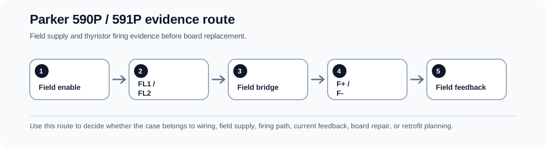
The field path starts with configuration and supply, not with the control board. The sequence is field-enable setting, FL1/FL2 supply, fuses or contact path, field bridge/regulator, F+ / F- motor field winding and field-current feedback. Each step can create a FIELD FAIL support request.
Field path evidence
| Path node | What it proves | Bad conclusion if skipped |
|---|---|---|
| Field-enable configuration | Whether the drive expects a field | Treating a parameter case as failed hardware |
| FL1 / FL2 and fuses | Whether field supply reaches the drive | Replacing boards when supply is absent |
| Field winding F+ / F- | Whether current can flow | Running armature into unsafe field loss |
| Field bridge/regulator | Whether the drive can produce field output | Blaming feedback too early |
| Field-current feedback | Whether measured field is reported correctly | Missing a detection-path fault |
Field record checklist
- Field-enable state
- FL1/FL2 photos
- F+/F- photos
- Fuse state
- Field voltage/current
- Feedback behaviour
Technical basis and reference documents
This is an independent editorial technical reference. Original manufacturer documentation remains controlling for installation, repair and commissioning decisions.
Primary product manual context for 590+ digital DC drive fault handling, safety boundaries and field/firing evidence routes.
Shows FIELD FAILED routing through field volts, external jumper positions, FL1/FL2 connection and wiring tightness before the drive is treated as failed.
A field technician case showing the real case behaviour behind mature SSD 590 Missing Pulse faults and current-waveform evidence requests.
Public support note connecting FIELD FAIL to field motor wiring, field fuses, field resistance checks and hardware repair boundary.
Turn this record into a qualified service request
A repair decision is much more reliable when the request includes the exact identity of the drive, the first fault evidence and the machine condition when the symptom appeared.
- Complete drive type code / MLFB or nameplate model
- Fault code, fault value and first event before reset
- When the event appears: power-up, enable, ramp, run, decel or stop
- Motor/cable connected or isolated during the symptom
- Visible board, option-card, module and connector identifiers
- Previous repair history, replacement parts and repeat-failure pattern