
Scope of this technical record
Armature current feedback path for 590P / 591P OVER I TRIP, current-loop instability and failed current-feedback evidence.
Current-feedback investigation must be planned around hazardous armature and line circuits. Do not probe internal circuits without qualified procedures.
590P armature current-feedback path
The feedback path explains why OVER I TRIP can be real current or a false-current signal.
590P armature current-feedback path
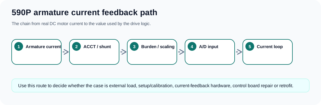
Path map
The feedback chain starts at real armature current and ends at the controller’s numerical current value. Along the way, the evidence can pass through an AC current transformer or equivalent feedback element, a plug or harness, burden/scaling components, filtering, low-voltage supplies and an A/D or current-processor boundary. A failure at any point can produce an OVER I TRIP without the motor actually drawing the displayed current.
Armature current-feedback path
| Path node | What to prove | Failure pattern |
|---|---|---|
| Real armature current | Does machine evidence match the trip? | Trip under genuine load, jam or motor fault |
| ACCT / feedback source | Is the sensor connected and matched? | Trip after connector movement or board service |
| Burden / scaling path | Is the current signal scaled correctly? | Implausible current display or failed autotune |
| Low-voltage feedback supply | Are feedback electronics powered cleanly? | Ripple, resets or unstable readings |
| A/D or processor boundary | Does the board interpret signal correctly? | Full-scale or frozen current with no physical basis |
| Current-loop command | Is the loop stable after autotune? | Oscillation or trip during current build-up |
Why the path matters
A DC drive can damage expensive hardware if a true overcurrent is ignored. But a false current signal can also waste money by sending a good bridge or motor for repair. The armature current-feedback page exists to keep both errors out of the support answer.
For repair requests, photographs of current-feedback connectors, board labels, prior repair marks and drive rating labels are as important as the alarm text. The evidence must show the whole feedback chain, not just the final fault message.
Field record checklist
- Armature current rating
- Trip timing
- ACCT / feedback connector photos
- Board labels
- Autotune result
- Displayed current value
- External current evidence
Technical basis and reference documents
This is an independent editorial technical reference. Original manufacturer documentation remains controlling for installation, repair and commissioning decisions.
Official source for OVER I TRIP: armature current above calibration value; possible causes include missing autotune, incorrect calibration and unstable current loop.
Official source for 590+ safety boundaries, permanent earthing, field/armature context and parameterised DC-drive operation.
Official converter reference describing current-feedback related trip protection and the importance of feedback hardware in external-stack cases.
Internal reviewed drawings used only as functional evidence for supply, feedback, burden, firing and bridge path mapping; original drawings are not redistributed.
Turn this record into a qualified service request
A repair decision is much more reliable when the request includes the exact identity of the drive, the first fault evidence and the machine condition when the symptom appeared.
- Complete drive type code / MLFB or nameplate model
- Fault code, fault value and first event before reset
- When the event appears: power-up, enable, ramp, run, decel or stop
- Motor/cable connected or isolated during the symptom
- Visible board, option-card, module and connector identifiers
- Previous repair history, replacement parts and repeat-failure pattern